Product
Book on product development. Metering, Microgrid OS, Batteries, Invertors, Solar panels
- Capability Evaluation Criteria
- Microgrid OS
- Metering
- Metering Evalutation
- Wired vs Wireless meters
- CalinMeter
- A2EI Data
- NFE metering strategy + Glen Street-EMS
- Phase Balancing Recommendation (Sezibwa)
- Sezibwa meter replacement log
- Storage
- Cost Analysis: Procurement and Shipment of 60kWh LFP BYD Batteries from China to Uganda
- Battery as a service Provider
- SRNE
- FENECon - Germany
- Solei Power - Uganda
- Arbitrage Tracker (gw-pi2, Sezibwa)
- Arbitrage Window and Thresholds (decision record)
- NFE Daily Brief (gw-pi2, Sezibwa)
- Macro outlook: shilling, rates and NFE (15 Oct 2026)
- Billing
- Microgrid Capability Map
- Microgrids 101
- OpenEMS
- Getting Started
- DDSU666 (Direct chint meter ) + mbpoll Command Reference
- Running OpenEMS Edge on a Raspberry PI
- DTSU666 3‑Phase + mbpoll Command Reference
- SRNE ASP48120SH3 (Direct Hybrid Inverter) + mbpoll Command Reference
- SRNE ASP48120SH3 Modbus Register Map (validated)
- SRNE ASP48120SH3 Safe Settings Write: design, registers, and commissioning (#53)
- SRNE charge/discharge scheduling registers (self-decoded, #67)
- SRNE phase balancing: big consumers on one phase trip the inverter on battery
- OpenEMS Backend InfluxDB Data Model and Edge-ID Collision
- Pre-Commissioning Process for CHINT Meters
- Towards a Framework for Autonomous Microgrids
- Metering protocols: DLMS/COSEM, OBIS, Modbus, MQTT (and NFE CHINT register map)
- Inverter-monitor notifications: hardening + tuning (ADR-012)
- SRNE TOU arbitrage: plan (#67)
Capability Evaluation Criteria
| Attribute |
Cost | Interoperability |
Long term relationship | Deployment readiness | Build Quality |
| 1 | over market price | proprietary standards, risk of vendor lock-in | cannot reliably communicate, needs aggressive follow up and management |
timeline unclear or unknown |
Questionable may need replacement anytime or unknown durability |
| 3 | close to or exactly at market price | use some open and proprietary standards |
can communicate reliably but needs incentives to do so |
timeline is known but is volatile or longer than what is needed |
Acceptable could last 2 to 3 years |
| 5 | under market price | fully using open standards | communicates reliably and incentives are already aligned |
timeline is known and predictable or within acceptable duration | Durable can last 3 years or more |
Microgrid OS
Monitoring and Steering assets on the microgrid
Microgrid OS Evaluation
| OS | Cost (money) | Interoperability | long term relationship | Deployment Readiness | Quality |
Features |
| NewSunRoad Stellar | ||||||
| Remot by Innovex | ||||||
| Inhemeter |
||||||
| GxF by LF Energy | ||||||
| MicroPower Manager | ||||||
| Hyphae by LF Energy | ||||||
| OpenEMS | ||||||
| Sunalyzer |
New Sun Road Stellar
Stellar seems to have all the capabilities we want from their website but Michael (CTO) confirms that he is not sure that the meters are are using are supported 100%. They can likely monitor usage data but may not be able to remote on/off. It is proprietary.
Remot by Innovex
The Innovex team has not been responsive to our email requests for more information about this. Also, their website seems to be frequently down.
Inhemeter
We were not about to get a demo or even an order for meters out of this company. Their meters are known to be good quality but I think they are not interested in working with us because we are a small new company.
GxF by LF energy
This project is actually a macrogrid OS that currently still being open sourced. A number of key components like the GUI for smart metering is not yet open sourced. It is worth watching because it has potential to run for a microgrid because it has smart metering and public lighting capabilities.
MicroPowerManager
This is one looks very promising. Open source and field tested. I think it's ripe for us to take to production and prove it out. It also has an associated battery management capability which makes this community seem like a good fit for NFE.
Hyphae by LF Energy
I think Hyphae has a bold vision for an autonomous microgrid. It currently only has peer to peer battery power interchange capabilities and no metering. Also not get field tested but has some simulation capabilities.
GxF Platform Evaluation
Overview
GxF is an opensource platform (set of capabilities; metering, public lighting) for distribution of power on a grid. It is currently being used by and was donated to the open source community by a Dutch utility company called Alliander.
Links
Here's some useful links from my discovery work on GxF
- Understanding it's capabilities
- Official docs
- Video Overview
- GxF on M1 Mac
- Microgrid Management Software
Next Steps
Continue deployment to digital ocean VM
- Start by reviewing all these packages and understanding which ones you want to deploy or explore whether it makes more sense to rebuild the latest release and deploy packages from that.
- To run the GXF (Grid eXchange Fabric) platform, you generally need only a subset of the packages published in the OSGP GitHub organization—specifically, those that are direct dependencies for the platform's core services and adapters.
- GXF is a modular system, and the required packages depend on your deployment goals. Commonly, the following package types are used:
- Core Platform Packages – These include the main server components, messaging infrastructure, shared libraries, and authentication modules.
- Protocol Adapters – Depending on your use case, you’ll need the adapters that communicate with your field devices (e.g., OSLP, DLMS, IEC61850).
- Domain and WS Adapters – These provide domain-specific logic and web service endpoints (e.g., smart metering, microgrids, public lighting).
- Shared Utilities – Supporting packages shared between multiple modules.
Steps to Determine Required Packages
- Review the GXF Deployment Documentation: The official [GXF deployment guide](https://github.com/OSGP/open-smart-grid-platformdocumentation) lists the core components and adapters you need to deploy for a standard platform.
- Match Packages to Components: Identify which packages correspond to those components (e.g., "osgp-adapter-domain-smart-metering", "osgp-adapter-ws-publiclighting", etc.).
Focus on Smart metering Use Case: One of the maintainers tells the application’s current design allows you to deploy only the smart metering components, along with some core GxF components. You’ll need the following components for smart metering:
- core GxF components:
- osgp-adapter-domain-admin
- osgp-adapter-domain-core
- osgp-adapter-ws-admin
- osgp-adapter-ws-core
- osgp-core
- osgp-logging
- Smart metering specific components
- osgp-adapter-domain-smartmetering
- osgp-adapter-ws-smartmetering
- osgp-protocol-adapter-dlms
- osgp-throttling-service
- osgp-secret-management
- Smart metering simulator
- osgp-simulator-dlms-triggered
- dlms-device-simulator-starter
These components do not contain any user interface but provide a SOAP interface for communication with the GxF platform. The user interface is currently not part of the open-source implementation.
- We could set up RESTful APIs and build a GUI we can use and contribute back to the community or we can also try to build a UI from the SOAP API available. Open to either, I don't know how much we can do with API only if we don't have a GUI.
Historical Context
From Sander (Maintainer). I recommend you join the project mailing list, introduce yourself (I already did) and use it to ask questions along the way.. I have found it very useful and Sander is very helpful in responding there.
We are currently in the process of creating an open-source containerized solution for deploying and testing GxF. With this solution it will be possible to run GxF locally in k3d - a lightweight wrapper to run k3s (a minimal Kubernetes distribution) in docker - and to run automated tests using cucumber. For this you will need at least 32 GB of RAM, 64 GB is preferable. The solution can be found here: https://github.com/OSGP/gxf-gitops. Container images can be found in https://github.com/orgs/OSGP/packages?repo_name=open-smart-grid-platform. Currently the gxf-gitops repository only contains the charts to deploy and test our flexible public lighting solution. The deployment of our smart metering solution is still work in progress.
As a side note, I would like to mention that the current smart metering implementation is specifically tailored to the Dutch market, so it would probably need several changes to make it operable outside of the Netherlands.
In the past we also used to have a distinct microgrids solution available, but as it was no longer used, we removed it from our codebase. However, the old microgrids components can still be found in the GitHub history:
- https://github.com/OSGP/open-smart-grid-platform/tree/release-5.28.0/osgp/platform/osgp-adapter-domain-microgrids
- https://github.com/OSGP/open-smart-grid-platform/tree/release-5.28.0/osgp/platform/osgp-adapter-ws-microgrids
- https://github.com/OSGP/open-smart-grid-platform/tree/release-5.28.0/osgp/protocol-adapter-iec61850
- https://github.com/OSGP/open-smart-grid-platform/tree/release-5.28.0/integration-tests/cucumber-tests-platform-microgrids
but they will require some serious dusting off to make them usable again.
Microgrid Design with OpenSolar
We have an OpenSolar NFE account, reach out to aaron.tushabe@nearlyfreeenergy.com for an invite.
⚙️ View and Bookmark all Training & Support Links
Webinar Recordings
🎥 MCS
Webinars
View availability and book our dedicated UK training sessions.
Purchasing & Supplier Integrations
🎥 Segen
Support
Get real-time live answers to your questions with our digital assistance
☀️ General Support Contact Form
Send enquiries, feedback and supporting information directly to our global 24 hour Mon - Fri support team. Tickets are the quickest most efficient way to receive support and guidance. Unfortunately, we can only offer very limited low-priority support via email.
Installers looking for 1-2-1 support can view our availability and book sessions directly. Click "Book a time" at the bottom of the page.
An extensive online library of videos and tutorials.
Finance Integrations
Selina (domestic payment plans)
- Email: tom.watson@selinafinance.co.uk
- Call: 020 4525 8044
- Register here
Phoenix Finance (domestic payment plans)
- Email: jono@phoenix-fc.co.uk
- Book meetings: https://calendly.com/jono-9
- Call: 01923 333 256
- Register here
Smart Ease (commercial payment plans)
- Email: enquiries@smartease.uk
- Call: 033 3404 0695
- Register here
Scaffolding Integration
API Integrations
Learn more and view documentation
Target Architecture

Metering
Metering Evalutation
| Attribute | Cost (money) | Interoperability | long term relationship | Deployment Readiness | Build Quality |
| Inhemeter |
3 | 5 | 3 | 3 | 5 |
| Gomelong Meter (no PLC meter with built-in relay) | |||||
| Sagewood Meters | |||||
| Calin Meter | ? | 5 | 5 | ? | 5 |
| Spark Meter | 3 | 1 | 3 | 1 | 5 |
| China Brandless Meter |
5 | 1 | 3 | 3 | 1 |
| iSmart Meter | 1 | 5 | 3 | 1 | 3 |
| Hoptele Meter | 3 | 5 | 5 | 5 | 3 |
Inhemeter
China/UG based OEM. Edwin Cho is our contact. 0 774 667667, +86 135 3210 1631. 1way Meter boxed FOB 46Usd
Cloud Vending System 100 USD per month up to 1000 meters
Free On Board (FOB)
Which means not including shipping and inland transport and any clearance fees
Sagewood
Sagewood is a UK based logistics supplier. +44 7831 135528 - Manoj
Got some feedback on this one . Here goes…
Hi Hilary, all good am still in china snd heading back tomrrow to uk.
China was on national holidays from 30 April to today May 5.
Now working on it.
I have discussed with the team - Due to small number of meters for the system, we suggest a cloud version so you don’t have to invest in hardware. Many endusers are doing this.
Meters we can handle but MOQ is around 2000 metres.
Or we can manufacture them to very with other orders. So you don’t have to worry about MOQ.
Allow me few days and I revert back.
Hoptele
China supplier / OEM. Single phase PLC meter. Wall mount with PLC support and inbuilt relay. DIN rail mount with PLC support but no inbuilt relay. 70 US per meter. No vending system.
Gomelong
China based supplier, has a local distributor in Uganda. Gomelong Meter (no PLC meter with built-in relay). May have none PLC option. Pricing for "digital meter" (probably with no relay) 127k UGX per unit.
Spark Meter
Kenya based. Proprietary system (Meters + AMI). 70 USD per meter. Comes with a DTU that requires line of sight to meters. 1 DTU per 2000 meters max. 600 USD per year per DTU.
Calinmeter
Have a DIN rail PLC with built-in relay. Waiting on quote. May also have AMI
iSmart
Found these ones online. They also have a PLC with built-in relay.
Wired vs Wireless meters
Wireless open standards
Comparison
| Protocol | Frequency | Range | Data Rate | Topology | Power Usage |
|---|---|---|---|---|---|
| Zigbee | 2.4 GHz, 915/868 MHz | Short | Up to 250 kbps | Mesh, Star | Very Low |
| LoRaWAN | 868/915 MHz | Long | 0.3–50 kbps | Star | Extremely Low |
| Wi-SUN | 868/915 MHz | Medium to Long | 50–300 kbps | Mesh | Low to Medium |
| Bluetooth LE | 2.4 GHz | Short | 125 kbps–2 Mbps | Star, Mesh | Very Low |
| IEEE 802.11ah | Sub-GHz (~900 MHz) | Medium | Up to Mbps | Star, Tree | Low |
| IEEE 802.15.4 | Various | Short–Medium | 20–250 kbps | Mesh, Star | Very Low |
| Thread | 2.4 GHz | Short | 250 kbps | Mesh | Very Low |
Recommended for Residential Microgrid Applications in Uganda:
-
LoRaWAN: If covering a large geographical area (kilometers), due to its excellent range, penetration, and low power use.
-
Wi-SUN: For robust, medium-to-large-scale smart metering networks, especially if a mesh topology is desirable.
-
Zigbee/Thread: Ideal for dense residential areas where devices (meters) are closer together, benefiting from low power and reliable mesh networking.
Wired Open standards
Comparison
| Protocol | Standard | OSI Layers | Medium | Topology | Range | Data Rate | Typical Application Areas | Remarks |
|---|---|---|---|---|---|---|---|---|
| G3-PLC | ITU-T G.9903 | Layers 1-2 | Power Lines | Mesh, Star | Up to several km | 2.4–35 kbps | Smart grids, AMI, smart meters | Robust, designed for noisy environments; supports IPv6, strong security |
| PRIME | ITU-T G.9904 | Layers 1-2 | Power Lines | Mesh, Star | Up to several km | 21–128 kbps | Smart metering, distribution automation | Optimized for higher-speed PLC, widely used in European smart meter rollouts |
| IEEE 1901.2 PLC | IEEE 1901.2 | Layers 1-2 | Power Lines | Mesh, Star | Up to several km | 2.4–500 kbps | Smart grids, smart cities | High interoperability, IPv6 support; ideal for utility and smart city deployments |
| M-Bus (Meter-Bus) | EN 13757 | Layers 1-2 | Twisted pair cable | Bus | Up to ~1 km | 0.3–38.4 kbps | Meter reading (water, heat, gas) | Widely used in Europe; reliable, low-cost wired solution |
| KNX | ISO/IEC 14543-3 | Layers 1-2 | Twisted pair cable | Bus, Star, Tree | Up to ~1 km | 9.6 kbps | Building automation, home control | Open standard for building automation, popular in Europe |
| BACnet MS/TP | ASHRAE 135 | Layers 1-2 | RS-485 twisted pair | Bus | Up to ~1.2 km | 9.6–115.2 kbps | Building automation, HVAC controls | Common in building and industrial automation; robust, scalable |
| Ethernet | IEEE 802.3 | Layers 1-2 | CAT5/CAT6 cable | Star, Tree | Up to ~100 m | 10 Mbps–100 Gbps | Networking backbone, smart buildings | High-speed, standard networking; widely supported across industries |
| RS-485 (EIA-485) | EIA-485 | Layers 1-2 | Twisted pair cable | Bus | Up to ~1.2 km | Up to 10 Mbps | Metering, industrial control systems | Simple, robust, widely used for serial data transmission |
| CAN Bus | ISO 11898 | Layers 1-2 | Twisted pair cable | Bus | Up to ~1 km | Up to 1 Mbps | Automotive, industrial automation | High reliability, robust error detection, common in harsh environments |
Recommended Wired Protocols for Residential Microgrid Metering (Uganda)
-
PLC-based (e.g., G3-PLC or IEEE 1901.2):
-
Ideal due to existing infrastructure (power lines).
-
Good for scalable, reliable deployments.
-
-
RS-485:
-
Robust, simple wiring suitable for smaller clusters.
-
Common for direct-wired connections (local clusters).
-
-
M-Bus:
-
Suitable if integrating gas, water, or heat metering alongside electricity
-
Comparison between wired and wireless
| Aspect | Wireless Option (Wi-SUN/LoRaWAN) | Wired Option (G3-PLC, RS-485) | Recommendation |
|---|---|---|---|
| Installation Cost | 🟢 Lower | 🔴 Higher (cabling, labor) | Wireless ✅ |
| Maintenance Cost | 🟡 Moderate (battery replacements) | 🟢 Low (no batteries required) | Wired ✅ |
| Reliability | 🟡 Medium (environment dependent) | 🟢 High (consistent, stable) | Wired ✅ |
| Scalability | 🟢 High (easy additions) | 🔴 Moderate to low (harder additions) | Wireless ✅ |
| Range/ Coverage | 🟢 Good (with repeaters) | 🟢 Excellent (using PLC) | Wired (PLC) ✅ |
| Security | 🟡 Good (depends on setup) | 🟢 Very Good | Wired ✅ |
| Installation Time | 🟢 Short | 🔴 Longer | Wireless ✅ |
| Physical disruption | 🟢 Minimal | 🔴 High (trenching, wiring) | Wireless ✅ |
💡 Recommended Choice: Hybrid or G3-PLC
📌 Primary Recommendation: G3-PLC (Wired)
Given your scenario (dense apartment blocks with existing electrical infrastructure and meters located closely on the ground floor), G3-PLC offers significant advantages:
-
Low Ongoing Maintenance: No batteries to manage.
-
High Reliability: Stable signal leveraging existing wiring.
-
Cost-effective (long-term): Minimal ongoing costs after initial installation.
-
Robust & secure: Highly suited for apartment complexes.
📌 Alternate Recommendation: Hybrid (PLC Backbone + Wireless Endpoints)
If flexibility or future expansions matter, consider a hybrid setup:
-
Use G3-PLC within each block to connect meters reliably to a local gateway.
-
Connect block gateways to a central system via wireless (Wi-SUN or LoRaWAN). This reduces physical disruption between buildings while maintaining the reliability within each block.
This hybrid method provides the best of both worlds—flexibility and low maintenance.
Links
CalinMeter
We got the API docs here: Calin_API_for_NFE.postman_collection.json
User Manuals
- User instructions for the CA168-S Single-phase electricity meter (1).pdf
- CA168 Din Rail Meter- Technical Specification (1).pdf
- Installation Guide - Calin LoraWAN Smart Meters.pdf
⚡ CalinMeter Status Codes – Postpaid Quick Reference & Action Guide
📑 Common Meter Status / Short Codes (Postpaid Use)
|
Code |
Meaning |
Action |
|---|---|---|
|
01 |
Cumulative total active kWh consumption |
Record/check usage trend |
|
14 |
Load threshold |
Compare with customer load, adjust if configured too low |
|
31 |
Current total active power |
Check load at moment of query |
|
35 |
Current total power factor |
If persistently low, investigate load/PF correction |
|
40 |
Number of meter cover open events |
Check tamper log; reseal if necessary |
|
41–45 |
Last 1st–5th cover open times |
Verify tamper history |
|
46 |
Number of overload trip events |
Review load demand; advise upgrade if frequent |
|
47–51 |
Last 1st–5th overload trip times |
Identify when overloads occurred |
|
52 |
Number of power down events |
Check supply reliability |
|
53–57 |
Last 1st–5th power down times |
Cross-check with outage records |
|
58 |
Number of phase down events |
Investigate supply-side issues |
|
87 |
Reason for relay disconnecting |
Use table below for action |
Perfect — let’s build a lookup table that maps your AMI responses (1000–1025) directly to the Code 87 disconnect sub-codes, with meaning and field action tailored for postpaid deployments.
⚡ AMI Operating Status Code Lookup (Postpaid Mode)
|
AMI Code |
Code 87 Sub-Code |
Meaning |
Field Action |
|---|---|---|---|
|
1000 |
00 |
Relay Closed (normal supply) |
✅ No action, meter supplying load. |
|
1001 |
1 |
No Credit |
(Ignore in postpaid) — not applicable. |
|
1003 |
3 |
Over Power (load exceeded threshold) |
Check load vs. configured trip limit; advise reduction or adjust threshold. |
|
1004 |
4 |
Relay Test |
No action needed — relay was tested. |
|
1005 |
5 |
Open Upper Cover (tamper) |
Reseal cover + enter clear tamper token. |
|
1006 |
6 |
Open Terminal Cover (tamper) |
Reseal cover + enter clear tamper token. |
|
1007 |
7 |
Remote Disconnect |
Confirm backend/HES instruction; reconnect if not intentional. |
|
1008 |
8 |
Not-active (meter not commissioned) |
Commission meter (default code: 12345). |
|
1009 |
9 |
Over Current |
Inspect load for surges; advise customer or adjust protection. |
|
1011 |
11 |
Over Voltage |
Supply voltage too high; report to utility/feeder operator. |
|
1012 |
12 |
Under Voltage |
Supply voltage too low; report to utility/feeder operator. |
|
1013 |
13 |
Current Reverse (possible tamper/wiring issue) |
Inspect wiring; correct polarity; clear tamper if needed. |
|
1014 |
14 |
Open Enclosure Cover (tamper) |
Reseal + enter clear tamper token. |
|
1015 |
15 |
Magnetic Field Interference (tamper) |
Investigate possible magnet tampering; clear tamper. |
|
1016 |
16 |
Current Imbalance |
Check for abnormal phase imbalance; troubleshoot load. |
|
1017 |
17 |
Neutral Line Interference |
Inspect neutral wiring/tamper. |
|
1018 |
18 |
Bypass (illegal connection) |
Investigate and escalate if confirmed. |
|
1021 |
21 |
Voltage Imbalance |
Investigate feeder phase imbalance. |
|
1022 |
22 |
Thermal Overload |
Meter overheating; check ventilation/load; allow cooling. |
|
1023 |
23 |
Low Power Factor |
Check load PF; recommend correction (capacitors). |
|
1024 |
24 |
Tariff Error |
Backend tariff configuration issue; escalate to AMI admin. |
|
1025 |
25 |
Remote Reconnect + Local Trip |
Local condition (e.g., overload/tamper) persists; troubleshoot before reconnection. |
✅ Key Notes for Postpaid Teams
-
Ignore credit-related codes (1001, and codes tied to tokens/residual amounts).
-
Focus on tamper (1005, 1006, 1014, 1015, 1018), load/power quality (1003, 1009, 1011–1013, 1016–1023), and backend issues (1007, 1024, 1025).
-
Always check AMI Code → Action before deciding if a site visit is required.
Would you like me to now regenerate the PDF reference card with this full 1000–1025 lookup table included, so your team doesn’t need to flip between guides?
✅ Quick Action Guide Summary
Examples
Example #1
You query the meter for meter operating status and you get back this
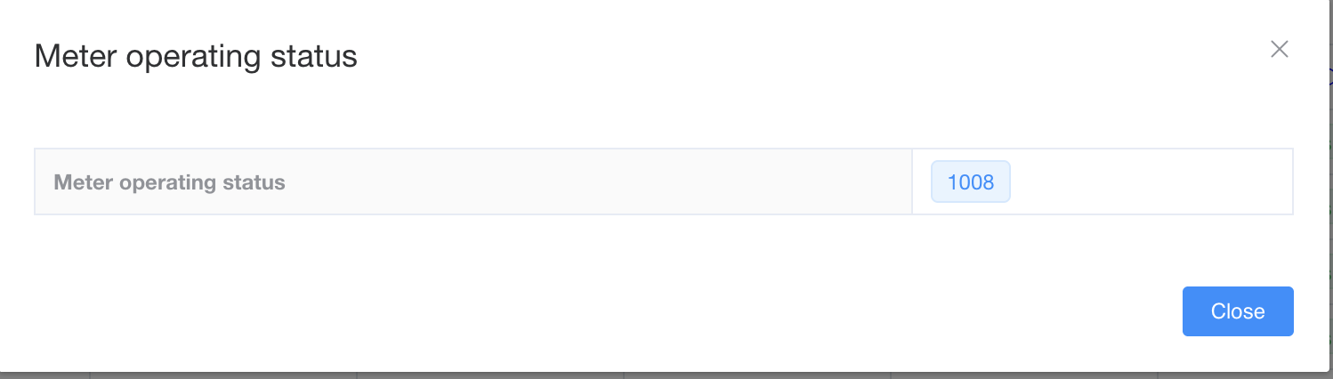
Answer
Meter operating status = 1008
Step 1: Interpret the Code
-
In many AMI/CalinMeter integrations, codes like 1000 and 1008 map directly to relay/disconnect statuses (Code 87 sub-codes).
-
1008 = Sub-code 8 under Code 87.
-
From the guide:
-
8 → “Not-active” → Meter not commissioned.
-
Step 2: What This Means in Postpaid Setup
-
The meter is physically installed, but it hasn’t been commissioned.
-
In this state, the meter will not supply power, regardless of load or tariff configuration.
Step 3: Field Action (from Quick Action Guide)
-
Action: Commission the meter using the commissioning token/code.
-
Default commissioning code is 12345.
-
Enter this via the CIU (Customer Interface Unit) or backend if supported.
-
-
Once successfully commissioned:
-
Tamper detection is activated.
-
Relay will close and supply will start flowing.
-
✅ Summary:
Your AMI response of 1008 means “Meter not commissioned.”
👉 To resolve: Enter 12345 (or your site-specific commissioning token) on the CIU/backend to activate the meter.
Example #2
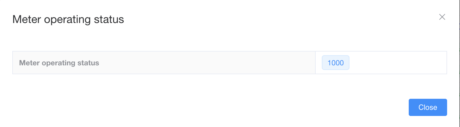
Answer
Great — let’s now map 1000 through the same guide.
Case: Meter operating status = 1000
Step 1: Interpret the Code
-
In the AMI integration, 1000 corresponds to Code 87 sub-code 00.
-
00 → “Relay Closed”.
Step 2: What This Means in Postpaid Setup
-
The meter is active and commissioned.
-
The relay is closed, meaning the meter is supplying electricity normally.
-
No tamper or abnormal condition is blocking supply.
Step 3: Field Action (from Quick Action Guide)
-
Action: No intervention needed.
-
Record this status if troubleshooting, since it confirms the meter is healthy and delivering power.
✅ Summary for your case:
Your AMI response of 1000 means “Relay Closed – supply ON.”
👉 Everything is normal; no technician action required.
⚡ So together:
-
1000 = Relay Closed (meter supplying power)
-
1008 = Not-active (meter not commissioned; activate with commissioning code)
A2EI Data
Thank you for showing interest in our data and our efforts here at the A2EI!
We are happy to provide you with our latest data releases from our Solar Killed the Generator Star Project in Nigeria, our clean cooking pilots, and our research into productive-use appliances in East Africa. Please find a detailed summary of each dataset and latest release below.
Please drop us a line via datadatadata@a2ei.org if you have any comments or questions, or in case you would like to unsubscribe from receiving updates.
Most recent data releases SKGS
06.04.2022 The A2EI set out to provide the sector with an open-source hardware
solar business system. Two years later, we have not only made the solar
generator available, but sold over 1,000 systems. Every solar
generator is sending real time data on consumption and system state,
which allows the A2EI to share millions of data points with the sector
as open-source data.
Please download our SKGS Project Update and Data Release Report here.
Download the associated data and readme here.
29.04.2020 To
date, we have over 215 smart meters (and counting) connected to small
scale generators and grids in Nigeria, located within multiple markets
across several regions.
You can download the raw data, the meter list as well as the README here.
Find some brief release notes here.
Please find the Executive Summary here.
02.06.2020 Please find our analysis of generator usage during COVID-19 here.
Latest data releases Clean Cooking
15.11.2021 In a new comprehensive data release report, the A2EI analyses the entire data collected by our smart meters monitoring the usage of electric pressure cookers (EPCs) by 100 pilot users in rural Tanzania from March 2020 to May 2021.
Please download the data release report here.
Download the data frames here.
Download the Readme here.
16.07.2021 The A2EI has been part of a feasibility study to pave the way for mass distribution of electric hotplates to rural households in Malawi. Please download the Study of Hotplate & Grid Use in Rural Malawi here and access the associated data here.
Latest data releases Productive Use
14.07.2021 We are sharing our learnings of successful ventures in the agricultural productive use appliance sector by our first "Entrepreneur in Residence", Imara Tech, and are proposing a way forward that we believe could increase the likelihood for successful product development. Download the summary of learnings here.
21.09.2020 The Access to Energy Institute has developed a systematic methodology and published a report to jointly discuss the question what makes or breaks a successful solar-powered productive-use appliance - and to help find solutions for successful adoption and scaling.
Download the report here.
Please find the associated data and materials here.
Your feedback is very warmly welcomed. We believe that sharing our data is paramount to unlocking further entrepreneurship and engineering, which in turn will help us crack the many nuts of providing a reliable, clean and affordable universal energy supply. In our efforts to deliver meaningful data, we need your feedback in order to collect further data points and to make adjustments to our current measuring practices.
For now, we wish you a wonderful day...and cheerful data crunching!
All the best,
your A2EI Team
NFE metering strategy + Glen Street-EMS
Authoritative page for NFE's role in the IEEE Smart Village meshEMS / Street-EMS initiative. Compiled 2026-08-10 from the Element room "Smart Village Energy Interest Group" (full history back to 2026-04-24), the ISV Dev Kit BOM sheet, isv.wiki, and the Rev B/C line diagrams. No customer PII or financial ledgers on this page by policy.
What it is
Not a standalone NFE product. It is NFE's seat in an IEEE Smart Village (ISV) open-source initiative called meshEMS, hardware-branded Street-EMS, started at an IEEE / NESL hackathon in April 2026. Hardware and firmware are led by Glenn Algie (10power.com / NESL); the software and standards side is led by Adam Sauer (ISV Tech Committee chair). The working venue is the Element/Matrix room "Smart Village Energy Interest Group".
meshEMS is open-source firmware on an ESP32-S3 / ESP32-P4 module doing OpenAMI two-way metering and control over secure MQTT into OpenEMS. Deployed as a street-pole or pedestal low-voltage feeder cabinet that meters AND controls every tenant, it is designed to replace the per-tenant DIN-rail meters and the OpenEMS Raspberry Pi with a single integrated 9x15 cm EMS board.
How it fits NFE
- Today (pilot): CHINT DDSU666 smart meters plus a Raspberry Pi gateway over Modbus RTU / RS485, feeding OpenEMS. Current pedestal cabinet is roughly 80 x 60 x 25 cm, about USD 150 locally.
- Next generation: the Street-EMS cabinet folds the 3-phase meter, the per-tenant meters and the Pi into one EMS board plus an SSR bank, shrinking the cabinet (cheaper, fits indoor locations, easier to secure from theft and weather) and adding per-tenant remote control and local energy-policy automation.
The cabinet (Rev C, 9-tenant, 3-phase LV feeder)
Signal flow left to right:
- Incoming LV feeder L1/L2/L3 + N + PE. Each phase: a 63A main breaker (QF1/QF2/QF3), a mains-usage CT (CT4/CT10/CT16), then a UKK80 terminal block fanning out to up to 6 tenant ways per phase.
- Three Ivy RCMs (RCM1/2/3), one residual-current monitor per phase, for continuous leakage and neutral insight. Modbus UART to RS485 adaptor.
- Nine contactors K1..K9 (3 tenants per phase) for per-tenant remote connect/disconnect, each with a tenant-usage CT (CT1,2,3,7,8,9,13,14,15).
- Controller on the cabinet door: "Street-EMS w RGBW" = 3 stacked CircuitSetup 6-channel CT meters = 18 channels (9 tenant + 3 mains + 6 spare).
- Two 8-channel opto-isolated zero-crossing SSRs drive the 9 contactor coils (9 control lines, 3x3 per phase, 240 Vac sensitive).
- Backplate Power PCB: fused, TVS surge protected, 3x Myrra 44122 240-to-9 Vac, giving 5V 2A and 12V 1A.
Legend (Rev B with legend): QF circuit breaker, CT current transformer, K contactor, UKK80 distribution terminal block, RCM residual current monitor, SSR solid-state relay, PCB printed circuit board, EVSE EV charger. 1P+N one phase plus neutral. RS485 / Modbus UART / I2C communications.
Decisions ratified in the room (2026-07-25):
- 1P over 1P+N for tenant breakers and contactors (1P is cheaper; do not switch neutral except for EV).
- 80A over 63A rating, chosen to leave room for a future EV station at a new location later this year.
- Rev B to Rev C added the legend; the diagram is deemed complete with only a few unlabelled wires to clarify at the workshop.
Still open: the make-before-break 80A neutral / phase-transfer balancer ("neutral rebalancer transfer method and apparatus") and the EVSE port are marked spare-room / in-progress.
Firmware and energy-policy vision (Glenn)
Local, IFTTT-style per-tenant automation in C/C++ on the ESP32, not just remote on/off:
- Triggers: prepaid-token expiry, over-voltage, over-current, over-kW, over-kWh, over-generation, over-storage.
- Actions: SSR disconnect (normally-closed contactor coil), SMS alert, RGBW LED or e-paper warning at the tenant box, a flash-warning cadence before cutoff, and a graceful post-sunset lighting-only allowance (about 10-20 W for a few hours from battery when storage allows).
- Policy model: each tenant has a JSON "mode" (safety vs prepaid-shutdown automations) stored in ESP32 SPIFFS or SD as a persistent energy-model cache.
- Grid insight: continuous per-phase leakage detection, neutral-imbalance alerts, phase-loss detection.
Cloudless village
An ESP32-P4 with its own Ethernet NIC acts as a per-feeder aggregation node. Street-EMS units LAN-hop along the feeder ("feeder hops") to run an in-village pay-go portal and full UX with no broadband. Optional LoRa / Meshtastic mesh and power-line communication on top; optional low-cost village camera / audio snapshots.
Standards and interoperability (OpenAMI)
OpenAMI is the "actionable energy telemetry" layer, the utility-facing layer above a village feeder. Built on DLMS/COSEM (IEC 62056), SunSpec Modbus/JSON, MQTT, IEEE 1547-2018 (DER interconnection) and IEEE 2030.5 (Smart Energy Profile). Village Metering goals: billing, remote disconnect, theft detection. EnAccess Foundation is extending the OpenAMI codeset. Reference: isv.wiki (repo github.com/overview-solutions/isv-ai-wiki, MIT).
The workshop (immediate driver of the ISV Dev Kit BOM)
IEEE ISV awarded Glenn and Adam a 4-session, 9-hour hands-on workshop (assemble an EMS in about 15 minutes each, assemble a cabinet, run code challenges). IEEE funds the parts BOM. Plan: build 15-20 EMS units and 3-5 multitenant cabinets for participants to take home (about USD 50 each). Parts pre-ship to Albert, the ISV lead in Nairobi (AliExpress China to Nairobi direct; small PCB parts hand-carried, PSUs prebuilt on site). BOM total about USD 2,377 per batch (see the ISV Dev Kit BOM sheet).
Venues: PAC2026 Nairobi (September) and OSEAS Kigali, Rwanda (October, about EUR 50).
NFE attendance (as of 2026-08-10): Dansturn and Dismas are going to Kenya (Nairobi). Aaron, now back in Uganda, could join them. Kigali remains a possibility. Glenn asked NFE to co-lead the cabinet builds.
People and orgs
Glenn Algie (10power.com / NESL / IEEE ISV, hardware + firmware; also WMAC.CLOUD New Zealand, REI Cameroon). Adam Sauer (ISV Tech Committee chair, meshems software + OpenAMI, runs isv.wiki). Aaron Tushabe, Hillary Arinda, Dansturn, Dismas (NFE). Albert (ISV Nairobi lead). Abiodun Okunola (ISV Africa regional lead). EnAccess Foundation, EPRI Open Source, NESL.
Sources
- Element room "Smart Village Energy Interest Group" (
#smartvillage:matrix.nearlyfreeenergy.com), full history from 2026-04-24. - ISV Dev Kit BOM (Google Sheet
1AeAUrfL-Fu_j3xsBPjY555B0huxV0nnMtRjkDTFPjTE). - Line diagrams saved at
NFE/smart village energy interest group/(Rev B with legend, Rev C editable + PDF). - isv.wiki;
github.com/energy-iot.
Open items
- Confirm the Rev C legend back to Glenn (he asked).
- Decide and mobilize the NFE workshop attendance (Nairobi confirmed for Dansturn + Dismas; Aaron + Kigali possible).
- Fill the detailed per-tenant "Behind the Meter" companion page.
Phase Balancing Recommendation (Sezibwa)
Recommendation for re-assigning Sezibwa's single-phase customers across the three phases of the SRNE three-phase inverter, to fix a severe load imbalance. Uses meter IDs; the site operator maps these to customers.
Implementation status (2026-08-24)
The two minimal phase-balancing moves were completed on the morning of 2026-08-24:
- Completed: meter 003 moved from L1 to L2.
- Completed: meter 009 moved from L2 to L3.
- Outstanding (optional): meter 004 remains on L3; the optional move from L3 to L1 was not completed.
The expected post-change distribution is L1 5.9 / L2 7.3 / L3 7.6 kWh/day (28 / 35 / 37 percent), based on the historical load profile. Live measurements should be reviewed after sufficient post-change data has accumulated to confirm the achieved balance.
Baseline before the change (the problem)
Before the 2026-08-24 reconnections, meter_100's per-phase energy and per-customer voltage matching (all high-confidence), the current assignment and daily load is:
| Phase | Load (kWh/day) | Share | Customer meters (kWh/day) |
|---|---|---|---|
| L1 | 10.4 | 50 percent | 002 (5.7), 003 (4.5), 008 (0.1), 011 (0.1) |
| L2 | 5.1 | 25 percent | 009 (2.3), 007 (1.6), 010 (1.2) |
| L3 | 5.3 | 25 percent | 006 (2.7), 005 (2.1), 004 (0.5) |
Total site load about 20.7 kWh/day, so the ideal is about 6.9 kWh/day per phase. L1 carries half the site while L2 and L3 carry a quarter each.
Root cause: the two largest consumers, meter 002 (5.7) and meter 003 (4.5), are both on L1. Together they are 10.2 kWh/day, which already exceeds a balanced phase on its own.
Updated meter reference (after 2026-08-24 phase balancing)
This table records the wiring after the two completed moves. Initials only (no full names, per the customer-data rule). Modbus address is the meter's slave address; serial is the physical meter serial. Energy figures are historical averages used for the recommendation, not post-change measurements.
| Meter | Modbus addr | Serial | Customer (initials) | Previous phase | Current phase | Change status | Historical kWh/day |
|---|---|---|---|---|---|---|---|
| meter_002 | 2 | 200326019929 | NP | L1 | L1 | Unchanged | 5.7 |
| meter_003 | 3 | 200326020101 | KFH | L1 | L2 | Moved 2026-08-24 | 4.5 |
| meter_004 | 4 | 200326020199 | AB | L3 | L3 | Optional L3→L1 move outstanding | 0.5 |
| meter_005 | 5 | 200326020128 | KFH | L3 | L3 | Unchanged | 2.1 |
| meter_006 | 6 | 200326020209 | WS | L3 | L3 | Unchanged | 2.7 |
| meter_007 | 7 | 210302003356 | JN | L2 | L2 | Unchanged | 1.6 |
| meter_008 | 8 | 200326019807 | PO | L1 | L1 | Unchanged | 0.1 |
| meter_009 | 9 | 250902040373 | DK | L2 | L3 | Moved 2026-08-24 | 2.3 |
| meter_010 | 10 | 250902040216 | SN | L2 | L2 | Unchanged | 1.2 |
| meter_011 | 11 | 250902040311 | (unmapped) | L1 | L1 | Unchanged | 0.1 |
KFH holds two meters (003 and 005), now split across L2 and L3. Names are looked up live from the customer database by serial; the logical-to-service-ID map in the logger configuration had 009/010 transposed, so the physical serial remains authoritative.
Why phase balance matters
- Voltage quality. L1 carries roughly twice the current of L2/L3, so it has the largest voltage drop. Customers on L1 see the lowest voltage (dimmer lights, more appliance stress) while L2/L3 sit high. Balancing evens the voltage across customers.
- Backup capacity. The SRNE is a three-phase inverter with a per-phase output limit. During a grid outage (battery backup), an overloaded L1 can hit its per-phase limit and trip or brown out even though L2 and L3 have spare capacity and the total is within the inverter rating. Balancing maximises the backup the site can actually deliver.
- Losses. Imbalance drives neutral current and extra I2R losses in the distribution.
Note: this does not affect the battery arbitrage or solar economics. The three-phase inverter time-shifts the site's total energy across all phases, so the savings analysis is unchanged. Phase balancing is a separate power-quality and backup-reliability issue.
Implemented recommendation (minimal moves)
The following two reconnections were completed on 2026-08-24:
- Completed: meter 003 (4.5 kWh/day) moved from L1 to L2 — the key move, separating the two big loads (002 and 003).
- Completed: meter 009 (2.3 kWh/day) moved from L2 to L3 — rebalances L2 after taking on 003.
Expected result based on the historical load profile:
| Phase | Before | After 2 moves |
|---|---|---|
| L1 | 10.4 (50 percent) | 5.9 (28 percent) |
| L2 | 5.1 (25 percent) | 7.3 (35 percent) |
| L3 | 5.3 (25 percent) | 7.6 (37 percent) |
The max-minus-min spread drops from 5.3 to 1.7 kWh/day.
Outstanding optional third move for near-perfect balance: meter 004 (0.5) remains on L3. Moving it from L3 to L1 would give L1 6.4 / L2 7.3 / L3 7.1 (31 / 35 / 34 percent), spread 0.9.
The calculation
- Total daily energy about 20.7 kWh across three phases, so ideal is 20.7 / 3 = 6.9 kWh/day per phase.
- Current spread (heaviest minus lightest): 10.4 - 5.1 = 5.3 kWh/day.
- After the two moves: 7.6 - 5.9 = 1.7 kWh/day.
- After the optional third move: 7.3 - 6.4 = 0.9 kWh/day.
Loads are from the same meter data used across the Sezibwa economic analysis (meter_100 aggregate plus per-customer meters, over the March to August 2026 window). Note that meters 003 and 005 belong to the same customer (two service points); moving 003 to L2 leaves that customer with one meter on L2 and one on L3, which is fine.
Data provenance
Underlying data: the aggregate meter meter_100 plus the 10 customer sub-meters, over 2026-03-19 to 2026-08-10, from the modbus energy-logger archive (sources: pi-direct and nextcloud-import), i.e. the pre- and early-OpenEMS period. Load basis is a conservative 21.3 kWh/day.
Note (2026-08-20): the site has since migrated to OpenEMS, which is now the live source. OpenEMS-sourced daily figures from mid-August show inconsistencies (the aggregate roughly doubled exactly at the source switchover, and on some days the customer-meter sum exceeds the aggregate), so they are treated as a data-quality issue to resolve before use; this analysis stays on the validated archive. The baseline phase assignments reflect wiring observed up to about May 2026. The meter reference and implementation status above were updated for the reconnections completed on 2026-08-24; OpenEMS measurements should be used to verify the resulting live balance.
Sezibwa meter replacement log
Sezibwa meter replacement log
One entry per customer meter swap at Sezibwa (gateway gw-pi2). Record every system that points at a meter serial, because each one must be switched separately: the OpenEMS gateway config, the customer app (meter_sources) and the billing engine (MBE device + household link). Customers are identified here by Modbus address and serial only.
Summary
| Date | Modbus address | Old serial | New serial | Status |
|---|---|---|---|---|
| 2026-09-14 | 7 | 210302003356 | 200326020197 | All systems switched 2026-09-24; closing 244.54 kWh, opening 0.31 kWh |
2026-09-14: address 7, 210302003356 to 200326020197
Why it was replaced. The old meter stopped answering on the meters bus on 2026-08-29 at 23:07 UTC (logger issue #82). It was later found physically absent. Its last register value seen on the backend was 229.35 kWh on 2026-09-04.
New meter. CHINT DDSU666 serial 200326020197, on Modbus address 7. The first backend data is from 2026-09-14; the register read 16.16 kWh on 2026-09-24.
Systems switched:
| System | Change | Date | Reference |
|---|---|---|---|
| OpenEMS gateway (gw-pi2) | New meter component meter200326020197 on unit 7 |
2026-09-14 | microgrid-gateway PR #68 |
| Customer app | meter_sources row repointed to meter200326020197/ActiveConsumptionEnergy, history start 2026-09-14; daily usage backfilled 14 to 24 Sep with the production backfill script (11 days, sums match the register) |
2026-09-24 | this page |
| Billing engine (MBE) | New device "(new meter)" added on edge sezibwa-rentals-gw-pi2 as a Consumption meter | 2026-09-24 | this page |
| Billing engine (MBE) | Household billing device changed to the new device (Change billing device); old device now unlinked; invoice meter serial field set to 200326020197 by hand | 2026-09-24 | MBE UI gap reported: serial does not follow a device change |
Closing and opening readings (from the swap thread, Element product room, 2026-09-14). Old meter 210302003356 read 244.54 kWh just before removal. New meter 200326020197 read 0.31 kWh at installation (about 12:15 EAT), on Modbus address 19. The old meter's register kept counting while it was off the bus, so there is no unmetered gap: its closing reading covers 30 Aug to 14 Sep.
September bill. The billing engine takes one meter per household per period, so bill this customer with one manual reading (manualReadings in the generate call) that joins the two meters:
| Start | End | kWh | |
|---|---|---|---|
| Old meter | 223.52 (August end, when it went silent) | 244.54 | 21.02 |
| New meter | 0.31 | reading at September close | end minus 0.31 |
| Manual reading to enter | 223.52 | 244.54 + (new end - 0.31) | sum of both |
Check first that the August bill really ended this customer at 223.52 kWh.
Watch. A stray 0.35 kWh value appears on 2026-09-14 under the old channel name. That was the new meter answering on address 7 before its component was renamed, not the old meter.
Storage
Batteries and invertor
Cost Analysis: Procurement and Shipment of 60kWh LFP BYD Batteries from China to Uganda
1. Executive Summary:
This report provides a comprehensive cost estimate for purchasing and shipping a 60kWh Lithium Iron Phosphate (LFP) battery pack manufactured by BYD from China to Uganda. The analysis encompasses the estimated purchase price in China, various shipping options and their associated costs, and the import duties and taxes applicable in Uganda. The total estimated cost is subject to considerable variation depending on factors such as the prevailing market price of batteries, the chosen shipping method (sea or air freight), and the specific import duties levied by the Ugandan authorities at the time of import. This report outlines a potential cost range to aid businesses in Uganda in their procurement planning and financial forecasting for such a significant component.
2. Introduction:
BYD (Build Your Dreams) stands as a prominent global manufacturer of rechargeable batteries, including Lithium-ion and LFP chemistries, with a significant presence in the electric vehicle and energy storage sectors.1 The company's LFP batteries are particularly recognized for their enhanced safety features and cost-effectiveness, making them a preferred choice for a wide array of applications, from electric vehicles to stationary energy storage systems.1 Given BYD's established position in the battery market, this report aims to provide a detailed cost analysis for an entity in Uganda seeking to procure a 60kWh LFP battery pack from this leading Chinese manufacturer. This analysis will delve into the primary cost drivers, including the initial purchase price of the batteries in China, the logistical expenses associated with shipping to Uganda, and the governmental levies in the form of taxes and duties imposed by both countries. Understanding these components is crucial for accurate budgeting and informed decision-making for any organization undertaking such an international procurement.
3. Estimated Purchase Cost of 60kWh BYD LFP Batteries in China:
The landscape of lithium-ion battery pricing in China has been characterized by a notable downward trend, primarily influenced by decreasing raw material costs and heightened competition among manufacturers.4 This trend is particularly evident in the pricing of LFP batteries, which generally exhibit a more competitive cost structure compared to Nickel Cobalt Manganese (NCM) batteries.6 Recent industry reports suggest that the price of LFP battery cells in China, which stood at approximately $70 per kilowatt-hour (kWh) in the near past, was anticipated to undergo substantial reductions throughout 2024, with further potential decreases projected for 2025.4 Some forecasts even indicated the possibility of LFP cell prices falling below $56/kWh by mid-2024 and potentially reaching as low as $36/kWh by 2025.4
Examining online marketplaces such as Alibaba and Made-in-China reveals a variety of BYD LFP battery products listed by different suppliers, with prices varying based on factors like capacity and the specific vendor.16 Given these fluctuating market conditions and supplier-specific pricing, it becomes apparent that a precise, fixed purchase price is difficult to ascertain. Instead, a more realistic approach involves considering a price range based on the available data.
Based on the per kWh price ranges identified in the research, the estimated purchase cost for a 60kWh BYD LFP battery pack in 2024 can be projected. Utilizing the lower end of the price spectrum at around $49/kWh 12 and the higher end at approximately $70/kWh 4, the following cost range can be estimated:
Table 1: Estimated Purchase Cost Range of 60kWh BYD LFP Batteries in China (2024)
| Price per kWh (USD) | Estimated Cost for 60kWh Pack (USD) |
| Low Estimate: 49 | 2,940 |
| Mid Estimate: 60 | 3,600 |
| High Estimate: 70 | 4,200 |
This suggests that the purchase cost for a 60kWh BYD LFP battery pack could range from approximately $2,940 to $4,200 based on 2024 price levels. It is important to note that potential price reductions anticipated for 2025 could further lower these estimates.
For sourcing these batteries, platforms like Alibaba and Made-in-China serve as potential avenues, hosting numerous suppliers and distributors of BYD batteries.16 Several specific companies have been identified as offering BYD battery products.16 Additionally, BYD itself operates an energy storage division, which could be a direct point of contact for procurement.25 While online platforms offer a broad selection of suppliers, engaging directly with BYD or their officially recognized distributors might provide enhanced assurance regarding product quality and potentially more favorable pricing terms, especially for substantial orders like a 60kWh battery pack.
4. Shipping Cost Analysis: China to Uganda:
Transporting a large and heavy item like a 60kWh battery pack from China to Uganda necessitates careful consideration of the available shipping methods, each with its own implications for cost and transit time. Sea freight generally emerges as the more economical option for such substantial cargo.37 Within sea freight, two primary options exist: Less than Container Load (LCL) for smaller shipments that don't fill an entire container, and Full Container Load (FCL) for larger volumes.37 The typical transit time for sea freight from China to Uganda ranges from 5 to 8 weeks.38
Conversely, air freight offers a significantly faster transit time, typically between 7 to 10 days for standard air freight and 2 to 4 days for express services.38 However, this speed comes at a considerably higher cost compared to sea freight.37
Estimating the precise shipping costs requires considering the weight and volume of the 60kWh LFP battery pack. Research suggests that a battery pack of this capacity can vary in weight depending on the manufacturer and design, ranging from approximately 438kg for a Tesla Model 3 battery 40 to over 700kg for a Delong battery pack.41
Based on these weight figures, the estimated cost for air freight, which is typically calculated per kilogram, can be projected. Using a cost range of $7.5 to $10 per kg 37, the air freight cost for a 60kWh battery pack could range from $3,285 (438kg * $7.5/kg) to $7,120 (712kg * $10/kg).
For sea freight, the cost is often determined by volume, particularly for LCL shipments, with rates ranging from $150 to $190 per cubic meter.37 While the exact volume of a 60kWh battery pack was not explicitly available in the research, its substantial size likely makes an FCL shipment (using a 20-foot container) a more practical approach. The cost for an FCL 20-foot container from China to Uganda is estimated to be between $4,000 and $6,000.37
Table 2: Estimated Shipping Cost Comparison (Sea vs. Air Freight)
| Shipping Method | Cost Metric | Estimated Cost (USD) | Transit Time |
| Sea Freight (LCL) | $150 - $190 / m³ | Requires Volume Data | 5 - 8 weeks |
| Sea Freight (FCL 20ft) | Per Container | $4,000 - $6,000 | 5 - 8 weeks |
| Air Freight | $7.5 - $10 / kg | $3,285 - $7,120 | 7 - 10 days (Std) |
The selection of the shipping method will have a significant impact on the total cost. Sea freight offers substantial cost savings but necessitates a longer lead time, while air freight provides speed at a considerable premium.
Engaging a freight forwarder is a common practice for international shipments to manage the complexities of logistics and customs procedures.37 These services typically involve additional fees covering documentation, customs clearance in China, and overall shipment coordination. Furthermore, it is important to anticipate potential surcharges such as fuel adjustments, port handling fees, and other miscellaneous charges that can add to the base shipping costs. Therefore, when budgeting for the shipment, an allowance for freight forwarder fees and these potential unforeseen surcharges should be included to ensure a more accurate overall cost estimation.
5. Tax and Duty Implications:
In China, the research material does not explicitly mention specific export taxes levied on batteries. While standard export procedures and minor administrative fees might be applicable, significant export duties on this commodity appear unlikely based on the provided information. Nevertheless, it is prudent to verify this with the chosen supplier or a freight forwarder based in China to preempt any unexpected charges at the point of export.
Uganda, on the other hand, has specific import duties and taxes that will apply to the incoming battery pack. Notably, Uganda recently imposed a 25% import duty on electric vehicles, hybrid vehicles, and electric motorcycles.48 While batteries are not explicitly listed in this category, their fundamental role as a core component in both electric vehicles and energy storage systems strongly suggests that they are highly likely to be subject to this new import duty. Under the East Africa Customs Union (EACU) common external tariff, most finished products attract a 25% duty, further supporting the likelihood of this tariff applying to the battery pack.50 This import duty is expected to be a significant contributor to the overall cost of importing the 60kWh LFP battery pack.
In addition to import duties, Uganda levies a Value Added Tax (VAT) at a standard rate of 18%.50 This VAT is typically calculated on the Cost, Insurance, and Freight (CIF) value of the imported goods, which includes the purchase price, shipping costs, and the import duty itself.52 Therefore, the 18% VAT will be applied on top of the combined cost of the battery, its shipment, and the 25% import duty, leading to a further increase in the total expenditure.
Other relevant taxes in Uganda include a 1.5% infrastructure tax on imports, designed to fund railway infrastructure development.50 Additionally, a 15% withholding tax may be applicable to imported goods and services, although the specific applicability to batteries warrants confirmation with the Ugandan tax authorities.50 While these taxes are individually lower than the import duty and VAT, they will collectively contribute to the overall tax burden associated with the import.
It is important to highlight that the Ugandan government offers potential tax exemptions and incentives for local manufacturers involved in the electric vehicle sector. Entities manufacturing electric vehicles, electric batteries, or charging equipment, and meeting specific criteria such as employing at least 80% Ugandan citizens, utilizing at least 80% locally sourced raw materials (where available), and meeting minimum investment thresholds, might be exempt from the 25% import duty and stamp duty.48 If the importing entity qualifies under these provisions, they could potentially realize significant reductions in the final cost.
To provide an estimated range for the import duties and taxes in Uganda, the following table illustrates the potential breakdown based on the low and high estimates for the purchase cost and shipping (using sea freight as the lower shipping cost):
Table 3: Breakdown of Estimated Ugandan Import Duties and Taxes (Based on Sea Freight)
| Item | Low Estimate (USD) | High Estimate (USD) |
| Estimated Value of Goods (Purchase + Shipping) | 6,940 | 10,200 |
| Import Duty (25% of Estimated Value) | 1,735 | 2,550 |
| VAT (18% of (Estimated Value + Import Duty)) | 1,561.20 | 2,295 |
| Infrastructure Tax (1.5% of Estimated Value) | 104.10 | 153 |
| Potential Withholding Tax (15% of Estimated Value) | 1,041 | 1,530 |
| Total Estimated Taxes and Duties | 4,441.30 | 6,528 |
Note: The "Estimated Value of Goods" in the Low Estimate scenario uses the low purchase cost ($2,940) + the low end of the FCL sea freight cost ($4,000). The High Estimate uses the high purchase cost ($4,200) + the high end of the FCL sea freight cost ($6,000).
6. Total Estimated Cost and Breakdown:
Consolidating the estimated purchase cost, shipping cost (considering both sea and air freight for a comprehensive range), and the total estimated taxes and duties, we can arrive at an overall cost projection:
Table 4: Consolidated Total Estimated Cost Range
| Cost Component | Low Estimate (USD) | High Estimate (USD) |
| Estimated Purchase Cost | 2,940 | 4,200 |
| Estimated Shipping Cost (Sea Freight) | 4,000 | 6,000 |
| Estimated Shipping Cost (Air Freight) | 3,285 | 7,120 |
| Estimated Taxes and Duties | 4,441.30 | 6,528 |
| Total Estimated Cost (Sea Freight) | 11,381.30 | 16,728 |
| Total Estimated Cost (Air Freight) | 10,666.30 | 17,848 |
The total estimated cost for purchasing and shipping a 60kWh LFP BYD battery pack from China to Uganda could range significantly, potentially from approximately $10,666.30 (low purchase cost + low air freight + low taxes/duties) to $17,848 (high purchase cost + high air freight + high taxes/duties). If sea freight is chosen, the range would be approximately $11,381.30 to $16,728.
7. Key Considerations and Recommendations:
For any entity in Uganda looking to undertake this procurement, several key considerations and recommendations should be taken into account:
- Supplier Negotiation: Actively engage in negotiations with potential battery suppliers in China to secure the most competitive purchase price, especially when dealing with larger order volumes.
- Incoterms: Clearly define and agree upon the Incoterms with the chosen supplier. These terms dictate the responsibilities and costs associated with transportation and delivery, including who bears the risk at different stages of the shipping process.
- Shipping Insurance: Secure adequate shipping insurance to protect against potential damage or loss of the valuable cargo during its transit from China to Uganda.
- Quality Control: Implement stringent quality control measures in China, preferably through on-site inspections before shipment, to ensure the battery pack meets the required technical specifications and quality standards.
- Customs Clearance in Uganda: Partner with a reputable and experienced customs broker in Uganda. Their expertise will be invaluable in navigating the import clearance procedures, ensuring compliance with all Ugandan regulations, and potentially expediting the process.
- Verification of Import Duties and Taxes: It is strongly recommended to directly contact the Uganda Revenue Authority (URA) or consult with a qualified tax professional in Uganda. This step is crucial to obtain the most up-to-date and accurate information regarding import duties, VAT rates, and the applicability of any potential exemptions for battery imports. The information provided in this report is based on currently available data but is subject to change.
- Exploring Local Suppliers: While the focus of this report is on importing from China, it might be worthwhile to briefly explore the possibility of sourcing similar batteries from local suppliers within Uganda or the broader East African region. However, the availability and cost-effectiveness of BYD LFP batteries through these channels may be limited.
- Long-Term Cost Analysis: When evaluating the overall cost, consider the long-term benefits associated with LFP batteries, such as their extended lifespan, high cycle life, and potentially lower maintenance requirements compared to other battery chemistries. These factors can contribute to a more favorable total cost of ownership over the operational life of the battery pack.
By carefully considering these recommendations and conducting thorough due diligence, the procuring entity in Uganda can better navigate the complexities and costs associated with importing a 60kWh LFP BYD battery pack from China.
Battery as a service Provider
SLS energy based in Rwanda
Cost: USD 4.40-6.48 kwh of system capacity available per month. Also depends on the duration of the lease.
SRNE
See product catalog here: https://www.srnesolar.com/
They have a factory showroom in Naguru.
Pricing from the factory showroom below. Full price list here:Uganda SRNE item price list.pdf
- 5.12 KW battery - 3.22m UGX
- 6kw inverter - 3.74m UGX
- 10kw inverter - 4.611m UGX
- 12kw inverter - 7.673m UGX
Quote from a thirrdparty local supplier is attached here. Quote-105 (1).pdf.
Datasheet here: SRNE_HESP series_EU_48V_3.6_6kW_230V_Single-Phase_Hybrid_Solar Storage Inverter_Datasheet_V1.2[20250618] (1).pdf
Modbus Protocol: SRNE Solar Charge Inverter MODBUS Protocol1.96 (1).pdf
FENECon - Germany
Solei Power - Uganda
They are offering LFP batteries (locally manufactured) with BMS.
They quoted:
Arbitrage Tracker (gw-pi2, Sezibwa)
Cumulative record of the TOU battery arbitrage on gw-pi2 (Sezibwa). Each night the inverter discharges the battery during a peak-tariff window and recharges it from the grid at the off-peak rate from 00:00. Daily progress goes to the Element business room; this page is the running record. It is rebuilt from the OpenEMS backend by scripts/arbitrage_tracker.py in the nfe-modbus-energy-logger repo.
Settings and why they were chosen: Arbitrage Window and Thresholds (decision record).
Last updated: 2026-10-15 06:32 EAT.
Totals
| Measure | Value |
|---|---|
| Nights armed | 15 |
| Energy shifted to peak | 65.6 kWh |
| Estimated net saving | 12,400 UGX |
| Average per armed night | 4.37 kWh, 827 UGX |
| Projected per month at that rate | 24,800 UGX |
Night by night
| Night | Config | Window | Start | SoC start | SoC end | Shifted (kWh) | Peak (kW) | Lowest pack (V) | Saving (UGX) | Recharge 00-06 (kWh) | Notes |
|---|---|---|---|---|---|---|---|---|---|---|---|
| 2026-09-26 | v12 | 22:00-23:59 | 22:03 | 78% | 48% | 3.08 | 6.1 | 50.96 | 582 | 5.9 | first armed night |
| 2026-09-27 | v13 | off | 0 | 0 | 4.5 | disarmed: SoC 65% after the 27 Sep overload outage | |||||
| 2026-09-28 | v14 | 21:30-23:30 | 21:33 | 87% | 64% | 2.28 | 4.6 | 51.45 | 432 | 4.1 | window moved to 21:30-23:30 |
| 2026-09-29 | v15 | off | 0 | 0 | 5.5 | disarmed: SoC 61% after the 05:15-07:51 grid outage | |||||
| 2026-09-30 | v17 | 21:00-23:00 | 21:03 | 87% | 60% | 2.75 | 6.3 | 50.94 | 519 | 4.5 | window 21:00-23:00, no more manual disarms |
| 2026-10-01 | v18 | off | 0 | 0 | 5.7 | skipped: two outages left SoC at 51% before the window | |||||
| 2026-10-02 | v18 | off | 0 | 0 | 1.7 | still disarmed (re-arm missed) | |||||
| 2026-10-03 | v19 | 21:00-23:00 | 21:03 | 64% | 38% | 2.64 | 4.4 | 51.10 | 499 | 7.0 | re-armed with the v17 profile |
| 2026-10-04 | v19 | 21:00-23:00 | 21:03 | 84% | 63% | 2.17 | 2.2 | 52.17 | 410 | 4.3 | |
| 2026-10-05 | v21 | 18:00-23:59 | 19:22 | 15% | 9% | 0.08 | 1.9 | 49.32 | 15 | 10.8 | driver rules live: start at 30% or above, floor 15%; 0.9 kWh of the discharge was during an outage (backup, not counted) |
| 2026-10-06 | v21 | 18:00-23:59 | 18:04 | 89% | 25% | 5.04 | 4.0 | 51.14 | 953 | 8.4 | 1.5 kWh of the discharge was during an outage (backup, not counted) |
| 2026-10-07 | v21 | 18:00-23:59 | 18:04 | 89% | 25% | 6.56 | 5.0 | 51.00 | 1,239 | 8.3 | |
| 2026-10-08 | v21 | 18:00-23:59 | 18:04 | 89% | 21% | 6.88 | 5.5 | 50.22 | 1,300 | 8.7 | |
| 2026-10-09 | v21 | 18:00-23:59 | 18:04 | 79% | 28% | 5.18 | 4.3 | 50.88 | 980 | 8.0 | |
| 2026-10-10 | v21 | 18:00-23:59 | 18:04 | 65% | 15% | 4.96 | 4.1 | 51.10 | 938 | 9.4 | |
| 2026-10-11 | v21 | 18:00-23:59 | 18:04 | 54% | 15% | 3.59 | 4.3 | 50.26 | 679 | 9.2 | |
| 2026-10-12 | v21 | 18:00-23:59 | 18:00 | 77% | 15% | 6.12 | 4.4 | 50.52 | 1,157 | 9.0 | |
| 2026-10-13 | v21 | 18:00-23:59 | 18:03 | 89% | 15% | 7.51 | 5.1 | 50.34 | 1,419 | 9.3 | |
| 2026-10-14 | v21 | 18:00-23:59 | 18:04 | 89% | 23% | 6.76 | 4.1 | 50.82 | 1,277 | 8.5 |
Outages and reliability
Every grid outage, with how the battery carried it and how much of the reserve that night's arbitrage had already used. This is the record for judging what the deeper discharge costs in backup.
| Measure | Value |
|---|---|
| Outages | 16 (27.4 h) |
| Outages where the site went dark | 1 |
| Outages that started after an arbitrage night, before the recharge | 0 |
| Of those, site went dark | 0 |
| Date | Start | End | Duration | SoC at start | Lowest SoC | Lowest pack (V) | Battery supplied (kWh) | Site dark | Arbitrage use before (kWh) | Notes |
|---|---|---|---|---|---|---|---|---|---|---|
| 2026-10-01 | 10:45 | 14:12 | 3h27 | 93% | 60% | 52.16 | 3.4 | no | ||
| 2026-10-01 | 20:20 | 20:42 | 0h22 | 56% | 52% | 51.92 | 0.5 | no | ||
| 2026-10-03 | 15:10 | 16:49 | 1h39 | 90% | 66% | 52.10 | 2.5 | no | ||
| 2026-10-04 | 16:35 | 16:52 | 0h17 | 90% | 87% | 52.60 | 0.3 | no | ||
| 2026-10-05 | 06:40 | 09:27 | 2h47 | 96% | 68% | 52.07 | 3.0 | no | ||
| 2026-10-05 | 10:35 | 13:44 | 3h09 | 66% | 37% | 51.70 | 2.9 | no | ||
| 2026-10-05 | 13:50 | 14:42 | 0h52 | 37% | 31% | 51.91 | 0.5 | no | ||
| 2026-10-05 | 15:25 | 17:17 | 1h52 | 30% | 15% | 50.91 | 1.6 | no | ||
| 2026-10-05 | 19:25 | 20:55 | 1h30 | 15% | 9% | 49.32 | 1.0 | yes, 48 min no data | ||
| 2026-10-06 | 19:20 | 20:06 | 0h46 | 81% | 64% | 52.00 | 1.7 | no | ||
| 2026-10-09 | 16:50 | 17:55 | 1h05 | 90% | 79% | 52.62 | 1.1 | no | ||
| 2026-10-10 | 10:45 | 10:47 | 0h02 | 93% | 93% | 52.92 | 0.0 | no | ||
| 2026-10-10 | 12:30 | 12:54 | 0h24 | 92% | 89% | 52.80 | 0.3 | no | ||
| 2026-10-10 | 15:15 | 17:39 | 2h24 | 88% | 65% | 52.32 | 2.4 | no | ||
| 2026-10-11 | 02:15 | 08:20 | 6h05 | 100% | 60% | 52.28 | 4.0 | no | 0.0 | |
| 2026-10-12 | 17:20 | 18:04 | 0h44 | 89% | 77% | 51.99 | 1.3 | no |
Where to tweak
- Unused battery headroom: the battery ends the window with an average 0.6 kWh above its floor (45% before the driver rules, 15% from v21) (118 UGX a night if shifted too).
- Peak energy still bought from the grid: 2.1 kWh a night between 18:00 and midnight falls outside the window. That is the ceiling for more shifting, limited by battery size and the backup reserve.
- Voltage margin: the lowest pack voltage so far is 49.32 V against the 50.4 V disarm trigger and 48.8 V inverter cut-off.
- Spread: each shifted kWh earns about 189 UGX net (666.5 peak minus 429.7 off-peak at 90% round trip). A new quarterly tariff changes this directly.
Method
- Shifted energy: battery discharge (ess0/ActivePower > 0) integrated over the configured window, with 10 minutes added at the end for the inverter clock lag. Only minutes with the grid present count; discharge during an outage is backup, not arbitrage, and is shown in the notes.
- Saving: shifted kWh at the peak rate, minus the off-peak cost of putting that energy back at 90% round-trip efficiency. It is energy only (no service charge, VAT or battery wear).
- Recharge: battery charging between 00:00 and 06:00. It includes refilling any evening outage use, so it can exceed the shifted energy.
- Config history: ADR-016 in the microgrid-gateway repo (v12 22:00-23:59, v13 off, v14 21:30-23:30 from 28 Sep, v17 21:00-23:00 from 30 Sep, v18 off 1-2 Oct, v19 re-armed from 3 Oct, v21 from 5 Oct: 18:00-23:59 with the driver's 30% start and 15% floor).
- Outage: a minute counts as an outage when any phase of the inverter's grid-side meter (meter0) reads under 150 V or the inverter reports machine state 3 (off grid). Minutes with no data during an outage mean the edge lost power, which means the site went dark; an outage counts as dark at 5 such minutes or when SoC fell to 10% (the inverter's cut-off point seen on 24 Sep).
- Arbitrage use before an outage: the energy that night's window took from the battery (grid present), for outages that start after the window and before 06:00. It is the backup the site did not have because of arbitrage. An outage that starts inside the window is marked, because from then on the discharge is backup.
Arbitrage Window and Thresholds (decision record)
This page records how the nightly TOU arbitrage window and battery thresholds at Sezibwa (gw-pi2) were chosen and changed. For the running night-by-night results see the Arbitrage Tracker. The engineering record is ADR-016 in the microgrid-gateway repository.
Current settings (from 30 Sep 2026)
| Setting | Value |
|---|---|
| Discharge window | 21:00 to 23:00 (config v17, microgrid-gateway PR #77) |
| Start threshold | 75% battery at window start, otherwise skip the night |
| Floor | 45%, stop discharging when reached |
| Recharge | from the grid at the off-peak rate from 00:00 (unchanged) |
How the thresholds are enforced. Until now, the 75% start rule and the 45% floor were enforced by hand, by deploying a "disarm" config and later a "re-arm" config. That meant a change and a deploy after every outage day. It stops now:
- The edge software will enforce both rules itself: skip the night if the battery is low at 21:00, stop at 45%, and resume the next night automatically. The work is tracked in microgrid-gateway issue #78.
- Until that is live, the window stays armed every night and nobody switches it off by hand. The inverter's own protections still apply (it switches the load to the grid at 10% when the grid is present, and cuts the load at 48.8 V).
Why 21:00 to 23:00
Site load inside each candidate window, over 75 to 77 nights (1 Jul to 28 Sep 2026). Battery use is corrected for the two real nights, which used about 20% less charge than the load alone predicts.
| Window | Average load | Heavy night (1 in 10) | Ends at, from a typical 86% start | Heavy nights ending below 45% | Ends at, from a 75% start |
|---|---|---|---|---|---|
| 21:30 to 23:30 (previous) | 3.5 kWh | 4.5 kWh | 59% | 0% | 48% |
| 21:00 to 23:00 (chosen) | 3.8 kWh | 4.8 kWh | 57% | 4% | 46% |
| 21:00 to 23:30 | 4.4 kWh | 5.3 kWh | 53% | 9% | 42% |
| 22:00 to 23:59 | 2.9 kWh | 4.0 kWh | about 64% | 0% | about 53% |
21:00 to 23:00 shifts slightly more energy than the previous window and stays clear of the floor on normal nights. 21:00 to 23:30 adds little energy, and from a 75% start it would end below the floor on most nights.
Typical start level. On normal evenings the battery is at about 86% at 21:00. It is lower only after a daytime outage (27 and 29 Sep started at 65% and 61%).
Outage timing. Of 14 outages seen from 25 Aug to 30 Sep (grid absent at least 30 minutes), 2 started between 21:00 and 06:00. The battery is refilled by about 01:30 after each night's discharge.
Value
Each kWh shifted from the peak rate (666.5 UGX) to the off-peak rate (429.7 UGX, at 90% round trip) saves about 189 UGX. Across the options above, arbitrage is worth roughly 15,000 to 20,000 UGX a month. The larger saving is solar (see "Solar Sizing Re-run, Sept 2026").
History
| Date | Config | Change |
|---|---|---|
| 26 Sep | v12 | First armed night, 22:00 to 23:59 |
| 27 Sep | v13 | Off after the overload outage (battery 65%) |
| 28 Sep | v14 | Window 21:30 to 23:30 |
| 29 Sep | v15 | Off after the morning outage (battery 61%) |
| 30 Sep | v16 | Re-armed 21:30 to 23:30 |
| 30 Sep | v17 | Window 21:00 to 23:00, start 75%, no more manual switch-offs |
NFE Daily Brief (gw-pi2, Sezibwa)
NFE daily brief
Written each morning by Claude Haiku from the day's data. Newest first, last 30 days.
2026-10-14
Daily brief: Sezibwa Rentals, 14 October 2026
Arbitrage window (18:00–23:59): The battery started at 89% and ended at 24%, discharging 6.7 kWh. Its lowest level for the day was 15%.
Grid outages: None. Power was off for 0 minutes.
Evening L3 voltage: The lowest L3 reading was 193.5 V. L3 spent 233 minutes below 207 V. This matches the known grid-side sag pattern.
Modbus errors: 275 for the day. Normal is about 100 plus the nightly burst from midnight to 2 AM, roughly 260 in total, so this is slightly higher than expected.
Needs attention: Modbus read errors were slightly above expected (275 vs. about 260). Check whether this repeats tomorrow.
2026-10-13
Daily brief, Sezibwa Rentals battery, 13 October 2026
The evening arbitrage window ran from 89% to 15% battery charge, discharging 7.5 kWh. The battery held the 15% floor.
There was no grid outage today (0 minutes).
Evening voltage on phase L3 was below 207 V for 189 minutes. The lowest L3 reading was 197.6 V. This matches the known evening pattern.
Modbus read errors totalled 230. That is within the normal range, which allows about 100 per day plus the nightly burst from midnight to 2 AM while the battery charges.
Needs attention: nothing.
Macro outlook: shilling, rates and NFE (15 Oct 2026)
Macro outlook: shilling, interest rates and NFE (15 Oct 2026)
Asked by Aaron in the NFE leads chat. Facts are from public reporting found on 15 Oct 2026 (links at the end). Where sources disagree or I could not confirm, it is marked UNVERIFIED. NFE's own cost and funding numbers are not all known to this note; the "what we need" list at the end says which.
What happened
- 14 Oct, special MPC meeting: Bank of Uganda raised the Central Bank Rate from 9.75% to 12% (+225 bp), the first move after eight holds. (Aaron's chat said 9.5%; the reports say 9.75%.) Reasons given: shilling down about 12% this year, higher oil prices, strong dollar demand from fuel importers, foreign investors leaving government bonds.
- Shilling: weakest in 33 years, about 4,143 to 4,153 per US dollar on 12 to 13 Oct. It reportedly strengthened more than 2% after the decision, but the reports give different levels (UNVERIFIED which is right). It passed 4,000 on 5 Oct.
- Inflation: headline 3.7% (June); energy, fuel and utilities 11.9% year on year, diesel up 37%. BoU now expects headline inflation to average 7 to 7.5% over the next 12 months (core 5.5 to 6%) and cut 2026/27 growth to 6 to 6.5%.
- Credit: the cash reserve requirement rose from 11% to 13.5% on 24 Sep, so banks have less to lend. In August, shilling loans averaged 17.9% and foreign-currency loans 7.5% (before the hike). Post-hike lending rates: not found.
- Electricity tariffs (ERA): Q4 2026 (Oct to Dec) appears unchanged from Q3 (domestic 779.4 UGX/kWh above the lifeline band, commercial 562.1). UNVERIFIED against the ERA PDF. ERA cited a 4.22% shilling depreciation when it held Q3.
How it reaches NFE
| Channel | Direction | Why |
|---|---|---|
| Hardware (inverters, batteries, panels, meters, Pis) | Cost up | Priced off the dollar. Local quotes follow the shilling within weeks. |
| Solar quote (Mudde, UGX 4,426,000 materials) | Cost up | About USD 1,067 at 4,150. See table below. |
| Customer tariff in MGM | Lagged support | MGM bands mirror ERA's domestic tariff (250 / 779.4 / 412 / 779.4 UGX/kWh, UGX 7,320 service charge, 18% VAT). ERA reviews quarterly and has named the exchange rate as an input, so retail prices follow the dollar with about one quarter of delay. |
| Arbitrage (peak 666.5 vs off-peak 429.7 UGX/kWh, Code 10.2) | Mild support | The saving is set in shillings, so it grows only if ERA raises tariffs. Today about 189 UGX per shifted kWh, roughly UGX 35,000 a month on one site at 6 kWh a night. Small against hardware costs. |
| Borrowing | Cost up | CBR at 12% points to higher shilling loan rates (assumption: not yet seen). Dollar loans look cheaper (7.5%) but turn expensive if the shilling keeps falling. |
| Customers (Sezibwa households) | Risk | Fuel and food inflation cuts what households can spend; September's pilot bill was UGX 552,197 for 8 households, so a few late payers matter. |
| Cloud and SaaS (Hetzner in EUR, Claude Team, API credits) | Cost up, small | Charged in foreign currency. The Claude credits (USD 1,000) and any USD grant gain value in shillings. |
| Grid reliability | Possible risk | Fuel cost and import pressure can strain UEDCL. Our 20:00 to 22:30 L3 sag pattern is already grid-side. |
Sensitivity: the Mudde solar materials quote (UGX 4,426,000 at 4,150/USD)
| UGX per USD | Materials cost (UGX) | Change |
|---|---|---|
| 3,950 | 4,212,700 | -5% |
| 4,150 | 4,426,000 | base |
| 4,500 | 4,799,300 | +8% |
| 4,800 | 5,119,200 | +16% |
| 5,000 | 5,332,500 | +20% |
The quote is valid to about 22 Oct. Labour is extra and local (Green Volta).
What I would do
- Decide the solar order before the quote lapses (about 22 Oct) or ask Mudde to hold the price in writing. Every 5% shilling move is about UGX 220,000 on materials.
- Buy hardware earlier rather than later for anything already planned (spare meters, Pis, a second inverter), while the shilling is firmer after the hike.
- Keep any USD funding in USD (grant, credits) until a shilling cost needs paying.
- Keep customer tariffs on the ERA bands and re-read the ERA schedule every quarter (next: the Q1 2027 schedule, due about the end of December).
- Avoid new shilling debt at the current rates unless the project pays back well inside a year; compare with a dollar-linked option only if income is dollar-linked.
- Watch the cash side of billing: track unpaid bills in MGM monthly, because households are the first to feel inflation.
What we need to finish this properly
- The next hardware order (items, supplier currency, timing) and any quotes in USD.
- How the grant (about USD 3,000) is held and when it is spent.
- Any loan or financing plan for the next site.
- Whether solar panels, inverters and batteries now carry import duty or VAT: not found in the 2026/27 budget reports (UNVERIFIED). Check URA and EAC tariff lines 8541, 8504 and 8507.
- Post-hike commercial lending rates (next BoU Financial Stability or bank rate releases).
Sources
- Pulse Uganda: Bank of Uganda raises CBR to 12% (14 Oct 2026)
- bne IntelliNews: Uganda central bank raises rate to 12% at emergency meeting as shilling hits record lows
- Investing.com: Uganda central bank raises rates to 12% to support shilling
- UBC: Bank of Uganda raises interest rate to 12% as inflation and shilling pressures mount (14 Oct 2026)
- Pulse Uganda: Uganda shilling falls to lowest level in 33 years
- UG Business: Bank lending grows at its fastest rate since 2015
- Monitor: High fuel prices push Uganda's inflation to 3.7 per cent
- ERA: Approves electricity tariffs for the third quarter of 2026; Monitor and Watchdog Uganda on Q4 2026 tariffs
- KPMG and Forvis Mazars: Uganda Budget Brief 2026/27
Billing
Billing and Payment System evalutation
| Attribute | Cost (money) | Interoperability | long term relationship | Deployment Readiness | Quality |
| Pesapal |
1 | 3 | 5 | 5 | 5 |
| Jumia Pay | |||||
| Pegasus |
|||||
| Kitegateway | 3 | 3 | 5 | 3 | 3 |
| Stripe Atlas | |||||
| Flutterwave | |||||
| Stanbic | 3 | 3 | 5 | 3 | 3 |
Pesapal
-
Saves Time & Cost: Rids off the time and resources of having to register orders & bookings manually.
-
Drive Sales 24/7: Push for sales all day as long as you are open without fear of overbookings
-
Reduce risk on Fraud: All payments are posted in real-time reducing risk of handling payments manually
-
You can run promotions on social media pages using links that will direct guests to place direct bookings to any property as well as to complete payment. i.e.https://payments.pesapal.com/wildwaterslodge
-
Arcadia Lodges -https://arcadialodges.reserveport.com/
-
Imperial Hotels -https://imperialhotels.reserveport.com/
-
BMK House - https://bmkhouse.reserveport.com/
-
Fast set up and training in 24 hours
-
Accept VISA , MasterCard & Mobile Money payments
-
Process MTN Mobile Money payments
-
Customer receives physical receipts for Mobile Money and card payments, you also retain the merchant copies to help in reconciliations.
-
Stable connection with both 4G + Wi-Fi
-
Virtual Cards from Booking.com & Expedia can be charged
-
Tap and Go feature
-
Next day settlement
-
Settlement to any Bank in Uganda
-
Very competitive transaction fees .
-
Access real-time reports
-
Branded receipt with your company logo
-
Integrate with any 3rd party POS system
-
Mitigate fraud and human error during reconciliation
-
Card rate per transaction- 2.5%
-
mobile money per transaction is 2%
-
Online Rate per transaction- 3.5%
-
Payment page set up-No cost
-
Certificate of incorporation
-
Form 20
-
Form 1
-
TIN certificate
-
IDs for the directors as per the form 20
-
Cancelled cheque leaf or Bank statement/ Bank letter confirming bank details
-
Completed signup form Pesapal Sign Up Form new.pdf
Questions from Aaron
Rates and Costs: In your current workflow, are these costs paid by customers (transparently) or charged to the merchant (hidden from the customer)? I pay my Yaka bill with MTN mobile money and when I pay for a token of 200k UGX, I am charged a 4150 UGX. I would like an approach where fees are transparent to the customer and not hidden. Customers are charged for every transaction they make see attached tariff Tarrif .png. In addition, merchant is charged commission of 3.5% per transaction
Payment links/Page: There's two options I would like to discuss here. There examples you shared for the lodges are one option. I would like to know if I can have the option of NFE appearing among the Pay Utility options on this page. Is that option available to us? This is not an available option, we can engage our developers on this.
Timelines for payment settlement: I would like to understand what your current average timelines are for settling funds to Merchants and Customers in the following cases
- Depositing funds on Merchant accounts after completion of a customer transaction. Let me know if these differ depending on the payment method the customer uses. Understanding these will help my team plan what our cashflow expectations if we decide to work with Pesapal. Settlement to merchant accounts takes 24hrs,we have developed this to have real time settlements to any bank or mobile money
- Refunding customers for transactions done in error or overpayment. How long before a customer receives their fund on their orginal form of payment when NFE initiates are refund through PesaPal. Reversals to customers take effect from the time we are notified
Documents required to be submitted: We are able to provide all these documents. I think you forgot to attach the sign-up form. See attached the sign up form
Lastly, in full transparency, this decision for our payments partner is still pending. We are currently evaluating other providers like Jumia Pay, Pegasus and setting up direct integrations with Telcos and Banks. We are aiming to make a decision on this by end of this week. Can we run a test account as you evaluate on the providers, this will give us the real feel.
Microgrid Capability Map
The Microgrid OS capability model describes what the platform enables people, devices and software to do. Capabilities are therefore named as behaviours — using verbs or object–verb phrases — rather than as domain nouns such as Assets, Alerts, Payments or Storage.
This keeps capability boundaries stable even as implementations change. For example, Measure Energy Use can be implemented by OpenEMS today and by other metering providers later; Collect Payments can be implemented by MTN MoMo, Airtel Money, bank integrations or manual reconciliation.
Important: the capability map and the Generation 1 / 2 / 3 model describe different things.
The capability map defines what the Microgrid OS does. The generation model describes how open, locally maintainable and community-controlled the current implementation of a capability is.
Capability map
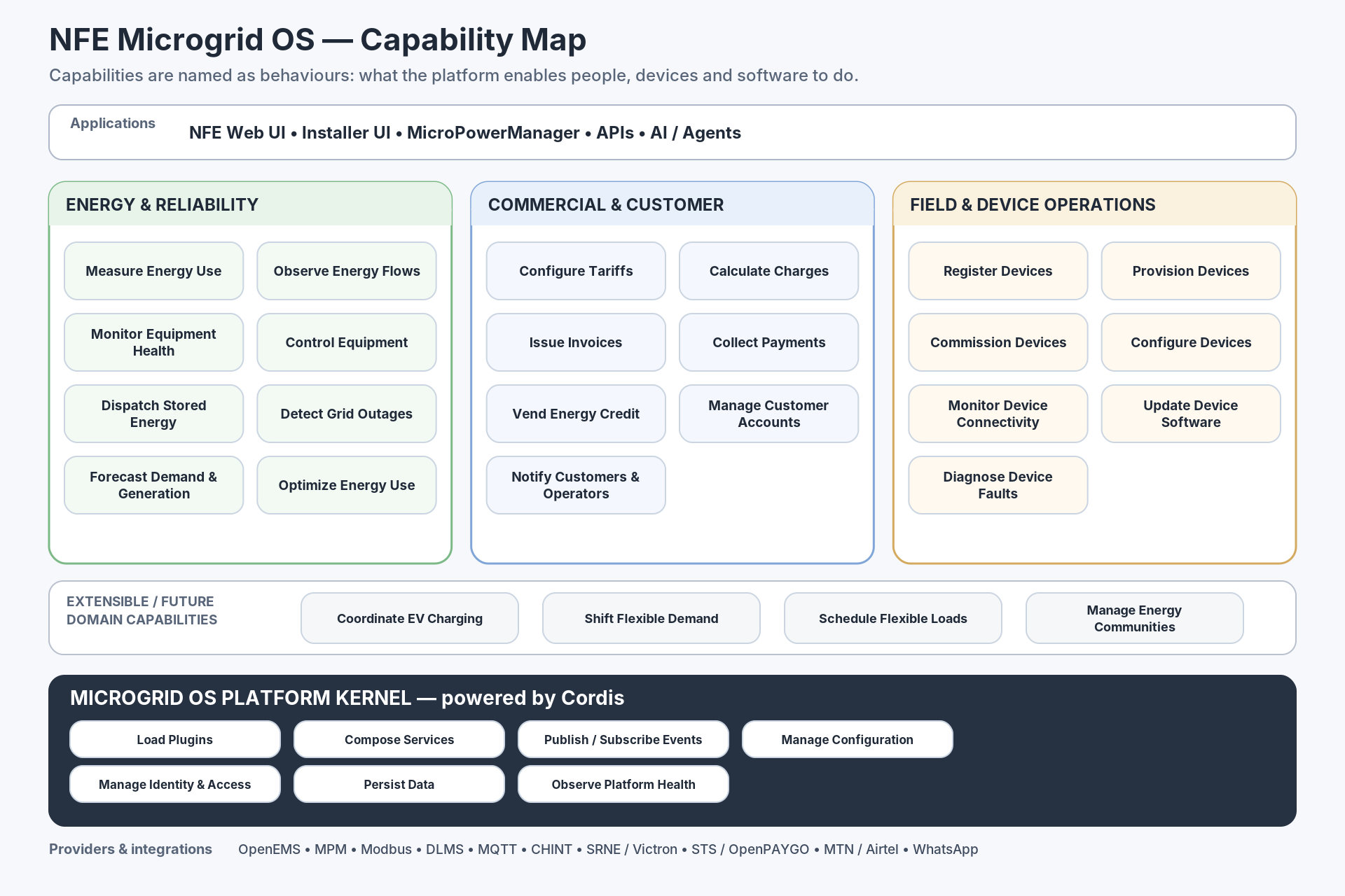
How this changes the previous map
| Previous noun-oriented area | Capability-oriented framing |
|---|---|
| Metering | Measure Energy Use |
| Storage | Dispatch Stored Energy, Observe Energy Flows, Monitor Equipment Health |
| Solar Generation | Observe Energy Flows, Forecast Generation, Control Equipment |
| Billing | Configure Tariffs, Calculate Charges, Issue Invoices |
| Payments | Collect Payments, Vend Energy Credit |
| Customer Relationship Management | Manage Customer Accounts, Notify Customers & Operators |
| Alerts | Detect Grid Outages, Diagnose Device Faults, Notify Customers & Operators |
| Assets | Register Devices, Provision Devices, Commission Devices, Configure Devices |
Generation model
Generation should be tracked per implementation of a capability, not baked into the capability name itself.
- Generation 1 — proprietary hardware/software; imported; expensive to acquire and repair; limited community control.
- Generation 2 — open-source software with locally obtainable but generally proprietary hardware; multiple implementers/SaaS providers are possible.
- Generation 3 — open hardware, firmware and software; equipment can be assembled and repaired locally; maximum community choice and maintainability.
This lets NFE move a capability from one implementation generation to another without changing the capability contract itself.
Our capabilities are currently evolving across 3 generations. See our roadmap for progress updates.
Microgrids 101
This page and Wikipedia go into great detail to describe the concept of a microgrid. I would like to expand on that. During one of the weekly LF Energy Hyphae community checkin calls. When I explained that the initial phase for NFE's pilot microgrid will only include sub-metering a handful of homes. My colleague commented that "Oh, so it won't really be a microgrid yet". That statement stuck with me because I infant think it would be a microgrid. Which brings us to the question I would like to address in this article. What do I mean when I say "microgrid".
Why definitions matter
Definitions generally matter because they help us communicate more clearly about the problem and how we are solving it. If we can agree on what we when when we say "microgrid" or "battery" then it makes it simpler to have conversations about which use-cases make sense for Hyphae's autonomous microgrid idea to address.
First principles
The term microgrid is a compound term. It consists of two terms micro and grid. I will start with the assertion that a microgrid is first a grid. If we are agreed there (pun not intended), then let's move on to define what we mean by grid.
A grid, in it's most primitive form, is really a set of at least two energy assets, connected, usually by physical energy conducting medium like a wire for a purpose. Let's look at the picture below.

The energy asset on the left (battery) is producing energy and the asset to the right is consuming energy. The two assets have been connected for a purpose and I think that's actually an a very simple example of a grid. Now this grid can include more than 2 assets and in the real world, there's often 100s of assets connected to a grid but for the sake of defining the term, I think this example will serve us well.
If you are still with me, let's move on to the preceding term, the micro term. This term adds a layer of meaning to the Grid term. I propose that the distiction between Micro and Macro is really about scope of monitoring and steering for the "owner(s)" of the grid. If the scope is considered small by the owner and exists within the context of a larger grid, then we have ourselves a microgrid.
Energy Assets
These exist in various forms but here's an oversimplified list Energy_Asset_Taxonomy.csv. I share it here to example one's imagination on the kind of things that can exist on a microgrid.
Supply-Side Assets (Energy Producers)
These generate or inject energy into the system.
|
Subtype |
Example Assets |
Notes |
|---|---|---|
|
Renewable Generators |
Solar panels, wind turbines |
Often variable in output |
|
Non-renewable Generators |
Diesel gensets, gas turbines |
Firm or dispatchable supply |
|
Co-generation Units |
CHP systems |
Produce electricity + heat |
Demand-Side Assets (Energy Consumers)
These draw energy from the system.
|
Subtype |
Example Assets |
Notes |
|---|---|---|
|
Residential Loads |
Lighting, HVAC, appliances |
Often flexible for DR programs |
|
Industrial Loads |
Motors, manufacturing equipment |
Usually larger and more steady |
|
Electric Vehicles |
While charging |
Can also act as supply (see V2G) |
Storage Assets (Bidirectional)
These can both store (consume) and release (supply) energy.
|
Subtype |
Example Assets |
Notes |
|---|---|---|
|
Battery Storage |
Lithium-ion, lead-acid |
Fast response, scalable |
|
Mechanical Storage |
Flywheels, pumped hydro |
Used in larger systems |
|
Thermal Storage |
Ice storage, molten salt |
Stores heat, not electricity |
Hybrid/Prosumer Assets
Assets that both consume and produce energy as part of normal operation.
|
Subtype |
Example Assets |
Notes |
|---|---|---|
|
Solar + Battery Systems |
Rooftop PV with integrated battery |
Common in homes & businesses |
|
EVs with V2G |
Electric Vehicles (bi-directional) |
Vehicle-to-grid capable |
|
Smart Appliances |
Can adjust operation dynamically |
May support DR/load shifting |
Monitoring & Steering Assets (Support Infrastructure)
These don’t directly consume or produce energy, but enable management.
|
Subtype |
Example Assets |
Notes |
|---|---|---|
|
Smart Meters |
Energy meters with comms |
Enable billing, monitoring |
|
IoT Sensors |
Voltage, temperature, fault sensors |
Support system diagnostics |
|
Controllers/EMS |
Inverters, EMS, SCADA systems |
Coordinate and control flow |
Monitoring and Steering the microgrid
This capabilities represent what the purpose for a microgrid can be. In the example of NFE's first phase of microgrid deployment. The purpose can be thought of as 3 part;
- for the owner (of the microgrid) to monitor energy consumptions patterns to inform additions of supply side assets like batteries in future so that energy can be more reliable for the community
- for the owner and consumers to bulk purchase electricity there by making it more affordable.
- for the owner and consumers to evolve the their experience of transacting on the grid. Prepaid vs postpaid vs credits to consumers.
The point here being that these capabilities of monitoring and steering (the assets) on the grid are a means to achieve a variety of purposes for the grid owner and other grid stakeholders.
The Autonomous Microgrid
This is what I think can be the vision for project Hyphae, to be able to simply define a start and end state for grid attributes we care about and have Hyphae monitor and steer the grid to the end state. For example, the end state could be 90% reliability for all demand side assets on the grid. Hyphae can then make sure that energy is being drawn or stored or cut off from some assets so that we can maintain a reliability of 90%.
That's what I imagine an autonomous microgrid should be capable of doing. There may be aspects of grid operations that will require manual human intervention like replacing a malfunctioning asset or making a payment for a bill but the more you think about it, the more you recorgnize that almost every aspect has potential to be automated to make the grid completely autonomous.
Levels of Microgrid Autonomy
I am thinking about how we can borrow from the 6 levels for Self driving cars to define levels for Microgrids..
TBD
OpenEMS
Getting Started
ZeroTier Remote Access Guide
This guide explains how to connect to the NFE Raspberry Pi from anywhere in the world using ZeroTier. It covers both SSH access and troubleshooting common issues.
Table of Contents
- Prerequisites
- Network Information
- Installing ZeroTier on Your Computer
- Joining the Network
- SSH Access to Raspberry Pi
- Troubleshooting
- Setting Up ZeroTier on a New Raspberry Pi
Prerequisites
Before starting, you need:
- A Mac or Windows laptop
- A ZeroTier account (free at https://my.zerotier.com)
- ZeroTier One installed on your computer
- Network authorization from the network administrator
Network Information
Network ID: 2873fd00f2d70904
Network Name: my-first-network
Raspberry Pi ZeroTier IP: 10.135.127.86
Raspberry Pi Username: nfetestpi2
Installing ZeroTier on Your Computer
Mac:
- Download ZeroTier One: https://www.zerotier.com/download/
- Install it normally
- After installation, the ZeroTier icon will appear in the top-right menu bar
Windows:
- Download ZeroTier from https://www.zerotier.com/download/
- Install and launch it
- ZeroTier icon will appear in the system tray
Joining the Network
Method 1: Using the ZeroTier Menu (Mac - Recommended)
- Click the ZeroTier icon in your menu bar
- You'll see "My Address:" with your device ID
- Click on the network ID
2873fd00f2d70904if it's already listed - Or select "Join New Network..." and enter:
2873fd00f2d70904 - The status will show "REQUESTING_CONFIGURATION"
Method 2: Using Command Line
Mac/Linux:
sudo zerotier-cli join 2873fd00f2d70904
Windows (run as Administrator):
zerotier-cli join 2873fd00f2d70904
Authorization
After joining, you need to be authorized:
- Contact the network administrator
- Provide them with your device's MAC address or Device ID
- They will authorize your device at https://my.zerotier.com
- Once authorized, your device will receive an IP address like
10.135.127.xxx
Verify Connection
Mac/Linux:
sudo zerotier-cli listnetworks
You should see:
200 listnetworks 2873fd00f2d70904 my-first-network ... OK PRIVATE ... 10.135.127.xxx/24
The status should show OK and you should have an IP address assigned.
SSH Access to Raspberry Pi
Once connected to the ZeroTier network, you can SSH to the Raspberry Pi:
ssh nfetestpi2@10.135.127.86
Enter the password when prompted.
Note: If you get a password prompt but it keeps failing, try using the -v flag for verbose output:
ssh -v nfetestpi2@10.135.127.86
Optional: Set Up SSH Keys (Recommended)
To avoid entering passwords every time:
- Generate SSH key on your computer (if you don't have one):
ssh-keygen -t ed25519 -C "your-email@example.com"
- Copy your public key:
cat ~/.ssh/id_ed25519.pub
- Add it to the Pi's authorized keys (via SSH or Raspberry Pi Connect):
mkdir -p ~/.ssh
nano ~/.ssh/authorized_keys
# Paste your public key, save and exit

# Set correct permissions
chmod 700 ~/.ssh
chmod 600 ~/.ssh/authorized_keys
- Now you can SSH without a password:
ssh nfetestpi2@10.135.127.86
Troubleshooting
Issue: ZeroTier shows "REQUESTING_CONFIGURATION"
Cause: Your device hasn't been authorized on the network yet.
Solution:
- Go to https://my.zerotier.com
- Log in and navigate to network
2873fd00f2d70904 - Click "Member Devices" tab
- Find your device and check the "Auth" checkbox
Issue: ZeroTier shows "OFFLINE"
Cause: ZeroTier service isn't running properly.
Solution for Mac:
# Restart ZeroTier service
sudo launchctl unload /Library/LaunchDaemons/com.zerotier.one.plist
sudo launchctl load /Library/LaunchDaemons/com.zerotier.one.plist

# Verify it's online
sudo zerotier-cli info
You should see:
200 info <device-id> 1.16.0 ONLINE
Solution for Windows:
- Restart the ZeroTier service from Services (services.msc)
- Or restart the ZeroTier One application
Issue: Can't ping or SSH to Raspberry Pi
Symptoms:
ping 10.135.127.86
# Shows: "No route to host" or "Request timeout"
Solutions:
- Check if ZeroTier is running on both devices:
sudo zerotier-cli info
# Should show: ONLINE
- Verify both devices are on the same network:
sudo zerotier-cli listnetworks
# Both should show network 2873fd00f2d70904 with status OK
-
Try changing WiFi networks: Sometimes the initial WiFi network blocks ZeroTier's peer-to-peer connections. Try connecting to a different WiFi network or mobile hotspot.
-
Check for RELAY connection:
sudo zerotier-cli peers
If the Pi shows as "RELAY" instead of "DIRECT", there's a NAT traversal issue. Try:
- Restarting ZeroTier on both devices
- Leaving and rejoining the network
- Changing WiFi networks
- Restart ZeroTier on both devices:
Mac:
sudo launchctl unload /Library/LaunchDaemons/com.zerotier.one.plist
sudo launchctl load /Library/LaunchDaemons/com.zerotier.one.plist
Raspberry Pi (via Raspberry Pi Connect):
sudo systemctl restart zerotier-one
- Leave old networks: If you have multiple networks joined, leave unused ones:
# List networks
sudo zerotier-cli listnetworks

# Leave old network
sudo zerotier-cli leave <old-network-id>
Issue: SSH password keeps failing
Solutions:
- Try verbose SSH to see what's happening:
ssh -v nfetestpi2@10.135.127.86
-
Make sure you're using the correct username (
nfetestpi2, notpi) -
Set up SSH keys instead (see SSH Keys section above)
Setting Up ZeroTier on a New Raspberry Pi
If you need to set up ZeroTier on a new Raspberry Pi, follow these steps:
Prerequisites
- Raspberry Pi with Raspberry Pi OS installed
- Internet connection
- Access to the Pi (via Raspberry Pi Connect, monitor/keyboard, or local SSH)
Installation Steps
- Install ZeroTier on the Raspberry Pi:
curl -s https://install.zerotier.com | sudo bash
- Join the network:
sudo zerotier-cli join 2873fd00f2d70904
- Verify the Pi joined:
sudo zerotier-cli listnetworks
You'll see status as "ACCESS_DENIED" initially.
- Go to https://my.zerotier.com
- Log in and navigate to network
2873fd00f2d70904 - Click "Member Devices" tab
- Find the new Pi device (you can identify it by the MAC address or hostname)
- Check the "Auth" checkbox
- Note the "Managed IP" assigned to the Pi (e.g.,
10.135.127.xxx)
- Verify connection:
sudo zerotier-cli listnetworks
Should now show:
200 listnetworks 2873fd00f2d70904 my-first-network ... OK PRIVATE ztxxxxxx 10.135.127.xxx/24
- Enable SSH (if not already enabled):
sudo systemctl enable ssh
sudo systemctl start ssh
- Make ZeroTier start on boot:
sudo systemctl enable zerotier-one
- Test connection from another device:
# From your computer (already on ZeroTier network)
ping <new-pi-ip>
ssh <username>@<new-pi-ip>
- Update this documentation with the new Pi's IP address!
Advanced: VNC Access (Remote Desktop)
If you need graphical access to the Raspberry Pi:
- Enable VNC on the Pi:
sudo raspi-config
# Navigate to: Interface Options → VNC → Enable
-
Install VNC Viewer on your computer: https://www.realvnc.com/en/connect/download/viewer/
-
Connect using the ZeroTier IP:
- Open VNC Viewer
- Enter:
10.135.127.86 - Enter Pi username and password
Quick Reference
Useful Commands
# Check ZeroTier status
sudo zerotier-cli info

# List joined networks
sudo zerotier-cli listnetworks

# Join a network
sudo zerotier-cli join <network-id>

# Leave a network
sudo zerotier-cli leave <network-id>

# Check peer connections
sudo zerotier-cli peers

# SSH to Raspberry Pi
ssh nfetestpi2@10.135.127.86
Network Details
- Network ID:
2873fd00f2d70904 - Network Name:
my-first-network - Pi IP:
10.135.127.86 - Pi Username:
nfetestpi2
Last updated: 2026-03-28
DDSU666 (Direct chint meter ) + mbpoll Command Reference
Version: 1.0
Prepared For: Field & Deployment Teams
Platform: Raspberry Pi / Linux
Tool: mbpoll
-
Purpose
This document explains how to communicate with the CHINT DDSU666 Direct Smart Meter using Modbus RTU and the mbpoll tool.
It covers:
• Reading electrical parameters
• Setting meter addresses
• Verifying communication
• Preparing for OpenEMS integration
2. Hardware & Software Requirements
Hardware
• DDSU666 (Direct Version)
• RS485 → USB Converter
• Raspberry Pi / Linux PC
• Correct RS485 wiring (A(converter)↔24(meter com-port terminal), B(converter)↔25(meter com-port terminal), GND recommended)
Software
Install mbpoll:
sudo apt update
sudo apt install mbpoll
Check serial port:
ls /dev/ttyUSB*
Example output:
/dev/ttyUSB0
3. Communication Parameters (Confirmed)
|
Parameter |
Value |
|
Protocol |
Modbus RTU |
|
Baud Rate |
9600 |
|
Data Bits |
8 |
|
Parity |
None |
|
Stop Bits |
2 |
|
Format |
8N2 |
|
Float Order |
Big Endian |
|
Addressing |
0-Based |
These parameters must always be used.
4. Standard mbpoll Format
All commands follow this format:
mbpoll -m rtu -b 9600 -P none -s 2 -t 4:float -B -0 -r <register> -c <count> /dev/ttyUSB0 -a <id> -1
Where:
• <register> = Modbus register
• <count> = Number of values
• <id> = Meter address (NO.)
5. Electrical Parameters
Summary:
Voltage: 0x2000
Current: 0x2002
Active Power: 0x2004
Power Factor: 0x200A
Frequency: 0x200E
Energy: 0x4000
5.1 Voltage (V) — Register 0x2000
Meter ID = 1
mbpoll -m rtu -b 9600 -P none -s 2 -t 4:float -B -0 \
-r 0x2000 -c 1 /dev/ttyUSB0 -a 1 -1
Meter ID = 2
mbpoll -m rtu -b 9600 -P none -s 2 -t 4:float -B -0 \
-r 0x2000 -c 1 /dev/ttyUSB0 -a 2 -1
5.2 Current (A) — Register 0x2002
Meter ID = 1
mbpoll -m rtu -b 9600 -P none -s 2 -t 4:float -B -0 \
-r 0x2002 -c 1 /dev/ttyUSB0 -a 1 -1
Meter ID = 2
mbpoll -m rtu -b 9600 -P none -s 2 -t 4:float -B -0 \
-r 0x2002 -c 1 /dev/ttyUSB0 -a 2 -1
5.3 Active Power — Register 0x2004
Meter ID = 1
mbpoll -m rtu -b 9600 -P none -s 2 -t 4:float -B -0 \
-r 0x2004 -c 1 /dev/ttyUSB0 -a 1 -1Meter ID = 2
mbpoll -m rtu -b 9600 -P none -s 2 -t 4:float -B -0 \
-r 0x2004 -c 1 /dev/ttyUSB0 -a 2 -1
5.4 Power Factor — Register 0x200A
Meter ID = 1
mbpoll -m rtu -b 9600 -P none -s 2 -t 4:float -B -0 \
-r 0x200A -c 1 /dev/ttyUSB0 -a 1 -1
Meter ID = 2
mbpoll -m rtu -b 9600 -P none -s 2 -t 4:float -B -0 \
-r 0x200A -c 1 /dev/ttyUSB0 -a 2 -1
5.5 Frequency (Hz) — Register 0x200E
Meter ID = 1
mbpoll -m rtu -b 9600 -P none -s 2 -t 4:float -B -0 \
-r 0x200E -c 1 /dev/ttyUSB0 -a 1 -1
Meter ID = 2
mbpoll -m rtu -b 9600 -P none -s 2 -t 4:float -B -0 \
-r 0x200E -c 1 /dev/ttyUSB0 -a 2 -1
5.6 Energy (kWh) — Register 0x4000
Meter ID = 1
mbpoll -m rtu -b 9600 -P none -s 2 -t 4:float -B -0 \
-r 0x4000 -c 1 /dev/ttyUSB0 -a 1 -1
Meter ID = 2
mbpoll -m rtu -b 9600 -P none -s 2 -t 4:float -B -0 \
-r 0x4000 -c 1 /dev/ttyUSB0 -a 2 -1
6. Reading Multiple Values
Use -c option to read multiple registers.
Example ( Voltage + Current Together)
mbpoll -m rtu -b 9600 -P none -s 2 -t 4:float -B -0 \
-r 0x2000 -c 2 /dev/ttyUSB0 -a 1 -1
7. Meter Address
Register: 0x0006mbpoll -m rtu -b 9600 -P none -s 2 -t 4:int16 -0 \
-r 0x0006 -c 1 /dev/ttyUSB0 -a 2 -1Example Output:
[6]: 2
8. Changing Address
- Only one meter connected.
- Power cycle after change.
Change Address (2 → 1)
mbpoll -m rtu -b 9600 -P none -s 2 -t 4:int16 -0 \
-r 0x0006 /dev/ttyUSB0 -a 2 -W -- 1
Power Cycle
Turn OFF → ON the meter.
Verify
mbpoll -m rtu -b 9600 -P none -s 2 -t 4:int16 -0 \
-r 0x0006 -c 1 /dev/ttyUSB0 -a 1 -1
9. Health Check
Voltage should be 220–240V.
mbpoll -m rtu -b 9600 -P none -s 2 -t 4:float -B -0 \
-r 0x2000 -c 1 /dev/ttyUSB0 -a 1 -1
10. Common Issues
Timeout Errors
• Duplicate IDs
• Wrong wiring
• Wrong stop bits
• Multiple meters during setup
Incorrect Float Values
Use -B option.
Current / Power = 0
Normal when:
• No load
• Bench testing
11. Deployment Workflow
For large installations:
• Connect one meter
• Convert to Modbus
• Set address
• Test voltage
• Install
• Repeat
• Never deploy duplicate addresses.
Connect → Configure → Test → Install
12. System Status
✔ Modbus Enabled
✔ 9600 8N2 Confirmed
✔ Big-Endian Floats
✔ Multi-meter Bus Working
✔ Ready for OpenEMS
Running OpenEMS Edge on a Raspberry PI
This guide explains how to:
-
Install and run OpenEMS Edge on a Raspberry Pi
-
Configure WebSocket + simulation
-
Run OpenEMS UI on a macOS machine (not on the Pi)
-
Connect the UI to the Edge over the internet
The structure is intentionally split into two clear parts:
-
PART A — Raspberry Pi (Edge)
-
PART B — macOS Machine (OpenEMS UI)
============================
PART A — Raspberry Pi (Edge)
============================
1. Raspberry Pi OS Setup (Headless)
Use Raspberry Pi Imager:
-
Device: Raspberry Pi 4
-
OS: Raspberry Pi OS Lite (64‑bit)
-
Configure:
-
Hostname
-
Username & password
-
Enable SSH
-
Configure Wi‑Fi
-
Enable Raspberry Pi Connect
-
Boot the Pi and connect via:
-
SSH
-
OR Raspberry Pi Connect
2. Install Java 21 (Temurin ARM64)
On the Pi:
sudo apt update
sudo apt install -y wget apt-transport-https gpg

wget -qO - https://packages.adoptium.net/artifactory/api/gpg/key/public \
 | gpg --dearmor | sudo tee /etc/apt/trusted.gpg.d/adoptium.gpg > /dev/null

echo "deb https://packages.adoptium.net/artifactory/deb \
$(awk -F= '/^VERSION_CODENAME/{print $2}' /etc/os-release) main" \
 | sudo tee /etc/apt/sources.list.d/adoptium.list

sudo apt update
sudo apt install -y temurin-21-jdk
Verify:
java -version
3. Install OpenEMS Edge
mkdir -p ~/downloads
cd ~/downloads
wget https://github.com/OpenEMS/openems/releases/download/2025.11.0/openems-edge.jar
sudo chmod +x openems-edge.jar

sudo mkdir -p /usr/lib/openems
sudo mv openems-edge.jar /usr/lib/openems/
sudo mkdir -p /etc/openems.d
4. Configure systemd Service
Create:
sudo nano /etc/systemd/system/openems.service
Paste:
[Unit]
Description=OpenEMS Edge
After=network.target

[Service]
User=root
Group=root
Type=notify
WorkingDirectory=/usr/lib/openems
ExecStart=/usr/bin/java -Dfelix.cm.dir=/etc/openems.d/ \
  -jar /usr/lib/openems/openems-edge.jar
SuccessExitStatus=143
Restart=always
RestartSec=10
WatchdogSec=60

[Install]
WantedBy=multi-user.target
Enable & start:
sudo systemctl daemon-reload
sudo systemctl enable openems
sudo systemctl start openems
Check:
systemctl status openems
5. Access OpenEMS Config Manager
On the Pi, open:
http://localhost:8080/system/console/configMgr
6. Add Required Components
In Config Manager:
-
Add a Scheduler (any default scheduler)
-
Add Controller.Api.Websocket
-
Port: 8085
-
Enabled: true
-
Restart Edge:
sudo systemctl restart openems
Verify WebSocket is listening:
sudo ss -lntp | grep 8085
You should see Java listening on port 8085.
7. (Optional) Add Simulation Components
In Config Manager, add:
-
Simulator ESS
-
Simulator Grid Meter
-
Simulator PV
Save and restart OpenEMS.
=====================================
PART B — macOS Machine (OpenEMS UI)
=====================================
1. Install Docker Desktop
brew install --cask docker
open -a Docker
Wait until Docker reports "Docker is running".
Verify:
docker version
You must see both Client and Server.
2. Clone OpenEMS Source
git clone -b 2025.11.0 https://github.com/OpenEMS/openems
cd openems
3. Build OpenEMS UI Image
docker build . \
  -t openems_ui \
  -f tools/docker/ui/Dockerfile.edge
4. Run OpenEMS UI
Replace YOUR_PI_IP with:
-
Public IP
-
OR VPN IP
-
OR Public DNS
Example:
docker container run \
  -e WEBSOCKET_HOST=YOUR_PI_IP \
  -p 80:80 \
  -p 443:443 \
  --restart unless-stopped \
  --name openems_ui_container \
  openems_ui
5. Open the UI
On your Mac:
http://localhost/login
Default login:
-
Username: admin
-
Password: admin
If UI shows "disconnected":
-
Confirm port 8085 is listening on the Pi
-
Confirm WebSocket controller exists
-
Confirm WEBSOCKET_HOST is correct
Why UI Runs on macOS and Edge Runs on Pi
-
Edge interacts with hardware and benefits from native systemd management
-
UI behaves like a stateless web application and is ideal for containerization
-
Separating them improves stability and flexibility
Troubleshooting
-
UI loads but no connection → check port 8085
-
Nothing listening on 8085 → WebSocket not configured
-
Docker errors on Mac → ensure Docker Desktop is running
Security Notes
-
Prefer VPN/tunnel (Tailscale/WireGuard) over port forwarding
-
Use SSH key-based authentication
-
Do not expose ConfigMgr (8080) publicly
You now have:
-
OpenEMS Edge running on Raspberry Pi
-
WebSocket enabled
-
Optional simulation components
-
OpenEMS UI running on macOS
-
UI connected over internet

DTSU666 3‑Phase + mbpoll Command Reference
🔌 Standard Communication Settings (DTSU666)
Most DTSU666 meters use:
Baud Rate : 9600
Data Bits : 8
Parity : None
Stop Bits : 2
Mode : Big‑endian
Table : Input Registers (FC04)
Base communication block used in all commands:
🧠 Critical Flags (Important)
| Flag | Meaning | Required? |
|---|---|---|
-t 3 |
Input Registers (Function 04) | ✅ Yes |
:float |
32‑bit floating point | ✅ Yes |
-B |
Big‑endian word order | ✅ Yes |
-0 |
Zero‑based addressing | ✅ Yes |
-a <id> |
Slave address | ✅ Yes |
-1 |
Poll once | Optional |
-l 5000 |
Poll every 5 seconds | Optional |
🔹 Phase‑to‑Neutral Voltages (L1‑N, L2‑N, L3‑N)
Register: 0x2006
-t 3:float -B -0 \
-r 0x2006 -c 3 \
/dev/ttyUSB0 -a 1 -1
🔹 Line‑to‑Line Voltages (L1‑L2, L2‑L3, L3‑L1)
Register: 0x2000
-t 3:float -B -0 \
-r 0x2000 -c 3 \
/dev/ttyUSB0 -a 1 -1
🔹 Phase Currents (L1, L2, L3)
Register: 0x200C
-t 3:float -B -0 \
-r 0x200C -c 3 \
/dev/ttyUSB0 -a 1 -1
🔹 Total Active Power (kW)
Register: 0x2012
-t 3:float -B -0 \
-r 0x2012 -c 1 \
/dev/ttyUSB0 -a 1 -1
🔹 Frequency (Hz)
Register: 0x2044
-t 3:float -B -0 \
-r 0x2044 -c 1 \
/dev/ttyUSB0 -a 1 -1
🔹 Total Active Energy (kWh)
Register: 0x4000
-t 3:float -B -0 \
-r 0x4000 -c 1 \
/dev/ttyUSB0 -a 1 -1
🔁 Continuous Polling Example (Every 5 Seconds)
-t 3:float -B -0 \
-r 0x2006 -c 1 \
-l 5000 \
/dev/ttyUSB0 -a 1
🔢 Change Slave Address (Only One Meter Connected)
⚠ Use Holding Registers (Function 03) for configuration.
Register: 0x002E
-t 4:int16 -0 \
-r 0x002E \
/dev/ttyUSB0 -a 1 -W -- 5
Changes slave ID from 1 → 5.
🧪 Quick Communication Test
Fastest health check:
-t 3:float -B -0 \
-r 0x2006 -c 1 \
/dev/ttyUSB0 -a 1 -1
If you see ~230V → communication confirmed.
🚨 Troubleshooting Quick Guide
| Symptom | Likely Cause |
|---|---|
| Timeout | Wrong address or wiring |
| 4200+ volts | Reading wrong register |
| -8192 values | Wrong data type |
| Nonsense numbers | Missing -B |
No /dev/ttyUSB0 |
USB‑RS485 not detected |
SRNE ASP48120SH3 (Direct Hybrid Inverter) + mbpoll Command Reference
Version: 1.1 Prepared For: Field & Deployment Teams Platform: Raspberry Pi / Linux Tool: mbpoll / pymodbus
1. Purpose
Complete reference for the SRNE ASP48120SH3 three-phase hybrid inverter over Modbus RTU: what can be READ, what can be WRITTEN, and the tested limits. Validated against the live unit at Nansana on 2026-07-21 (slave address 1).
2. Hardware & Software Requirements
- SRNE ASP48120SH3, RS485 to USB converter (CH340), Raspberry Pi / Linux PC.
- Wiring: A(converter) to WiFi-port RJ45 pin 7 (RS485-A), B to pin 8 (RS485-B), GND to pin 2. The WiFi port carries the monitoring bus; the RS485/CAN port is for the battery BMS.
- Install:
sudo apt install mbpolland/orpip install pymodbus.
3. Serial parameters and function codes
- 9600 baud, 8 data bits, No parity, 1 stop bit (8N1). Slave address 1.
- READ: function code 03 (holding registers). 16-bit registers with scale factors (not 32-bit floats).
- WRITE: BOTH FC06 (write single) and FC16 (write multiple) are supported and tested. Note: the CHINT meters reject FC06, the inverter does NOT.
- mbpoll read flags:
-b 9600 -P none -s 1 -t 4 -0.
4. Reading values (exhaustive, all ranges respond)
Every documented range answers FC03. Ranges (SRNE V1.7 segment map, confirmed on this unit):
Product info (P00), 0x0000 to 0x0049
- 0x000B machine type = 4 (integrated inverter-controller)
- 0x0014 software version = 925
- 0x001A RS485 address = 1 (read only)
Controller / battery (P01), 0x0100 to 0x0122
- 0x0100 SOC (%), 0x0101 battery V (x0.1), 0x0102 battery I (x0.1 signed, + charge / - discharge), 0x0103 device temp (reads 0, unused)
- 0x0104 to 0x0106 DC load V/I/P (0, no DC load on this unit), 0x0107 to 0x0111 PV panels 1/2 (0, no PV), 0x010B charge state (1 = quick charge)
Inverter (P02), 0x0200 to 0x0237 (the main live telemetry, see the register-map page)
- state 0x0210, bus 0x0212, grid+inverter phase A 0x0213 to 0x0218, load 0x0219 to 0x021F, heat-sinks 0x0220 to 0x0223, PBus/NBus 0x0228/0x0229, 3-phase B/C V/I 0x022A to 0x022F, 3-phase B/C load 0x0230 to 0x0237.
Settings / parameters, 0xE001 to 0xE02D (writable, see section 5). Raw values present; battery voltage thresholds around 0xE006 to 0xE00E appear as 48V-system values (register/10 x 4), e.g. 144 = 57.6 V. Exact per-register meaning is TBD from the ASP settings doc.
Settings F, 0xF000 to 0xF01F: additional parameters (raw values present).
Control commands, 0xDF00 to 0xDF09: write-only, read back as 0.
Example reads (mbpoll):
# battery block 0x0100 (dec 256), 4 regs
mbpoll -m rtu -b 9600 -P none -s 1 -t 4 -0 -r 256 -c 4 -a 1 -1 <port>
# inverter block 0x0210 (dec 528), 32 regs
mbpoll -m rtu -b 9600 -P none -s 1 -t 4 -0 -r 528 -c 32 -a 1 -1 <port>
# settings 0xE001 (dec 57345), 45 regs
mbpoll -m rtu -b 9600 -P none -s 1 -t 4 -0 -r 57345 -c 45 -a 1 -1 <port>
5. Writing values (tested 2026-07-21)
The inverter accepts BOTH FC06 and FC16 and enforces a permission model:
- Read-only registers (telemetry, product info, e.g. 0x001A) REJECT writes with exception code 7 ("parameter is read only"). Tested.
- Settings registers (0xE0xx) ACCEPT writes (both FC06 and FC16), with no password or run-state lock on the tested registers (0xE015, 0xE01F, 0xE024). Tested via no-op write-back (wrote the current value, confirmed unchanged).
- Control commands (0xDF00 to 0xDF09) are write-only actions. NOT fired on the live unit because it feeds customers. Documented below.
Exception code table (SRNE V1.7): 1 illegal function, 2 illegal data address, 3 illegal data value, 4 operation failed, 5 password error, 7 read only, 8 cannot change while running, 9 password protection, 10 length error, 11 permission denied.
Control command registers (DANGEROUS on a live system, documented only):
- 0xDF00 power ON/OFF: 1 = on, 0 = off. OFF cuts inverter output, do NOT fire while it feeds customers.
- 0xDF01 reset: 1 = reset.
- 0xDF02 restore defaults: 0xAA wipes all settings.
- 0xDF03 clear current alarm: 1.
- 0xDF04 clear statistics: 1.
- 0xDF05 clear history: 1.
- 0xDF08 sleep/run: 0x5A5A sleep, 0xA5A5 run.
How to write:
# mbpoll FC06 (write single): value as the last argument
mbpoll -m rtu -b 9600 -P none -s 1 -t 4 -0 -r <dec_addr> -a 1 <port> <value>

# pymodbus
client.write_register(address=REG, value=V, device_id=1)     # FC06
client.write_registers(address=REG, values=[V], device_id=1) # FC16
6. Tested limits summary
- CAN: read every range over FC03; write settings 0xE0xx with FC06 or FC16; read-only registers are protected (code 7).
- CAUTION: control commands 0xDF00 to 0xDF09 are live actions (power, reset, restore). Documented, NOT fired on the customer-feeding unit. Only fire with an outage window and explicit sign-off.
- UNKNOWN / next: exact meaning of each 0xE0xx and 0xF0xx setting (needs the ASP settings doc or careful change-and-revert testing offline); machine-state codes other than 2 (verify by observing transitions).
7. Preparing for OpenEMS integration
The validated telemetry map is a declarative table in src/inverter/registers.py (nfe-modbus-energy-logger), grouped by OpenEMS nature (ElectricityMeter grid/backup, SymmetricEss battery, OffGridBatteryInverter state). It maps 1:1 to a GoodWe-style defineModbusProtocol (FC3ReadRegistersTask + word elements + SCALE_FACTOR). Control writes map to FC16WriteRegistersTask on the 0xDF00 area and 0xE0xx settings.
SRNE ASP48120SH3 Modbus Register Map (validated)
Validated Modbus register map for the SRNE ASP48120SH3 three-phase hybrid inverter, verified register-by-register against the live Nansana unit, including a grid-off / grid-on transition test on 2026-07-27 that resolved the previously-unknown registers and corrected the battery-current sign.
Bus: RS485, 9600 8N1, function code 03 (read holding registers), slave address 1.
Source of truth (code): src/inverter/registers.py in nfe-modbus-energy-logger.
Valid register ranges (probed live)
- P00 product info: 0x0000 to 0x0049
- P01 battery / DC: 0x0100 to 0x0111
- P02 inverter telemetry: 0x0200 to 0x023F (0x0240 and beyond return "Illegal data address")
- P03 control commands: 0xDF00 to 0xDF09 (write-only, read back 0)
- Settings E (writable params): 0xE001 to 0xE02D ; Settings F: 0xF000 to 0xF01F
Live telemetry, full per-phase - VERIFIED
| quantity | phase A | phase B | phase C | notes |
|---|---|---|---|---|
| grid voltage | 0x0213 | 0x022A | 0x022B | x0.1 V (all go to 0 when grid is off) |
| grid current | 0x0214 | 0x0238 | 0x0239 | x0.1 A. B/C live in the extended block, CONFIRMED grid-side by the transition test |
| grid frequency | 0x0215 | - | - | x0.01 Hz |
| grid active power | 0x023A | 0x023B | 0x023C | W (extended block, grid-side) |
| inverter voltage | 0x0216 | 0x022C | 0x022D | x0.1 V |
| inverter current | 0x0217 | 0x022E | 0x022F | x0.1 A (rises when off-grid, inverter sources the load) |
| inverter frequency | 0x0218 | - | - | x0.01 Hz |
| load current | 0x0219 | 0x0230 | 0x0231 | x0.1 A (load-side, holds through the transition) |
| load active power | 0x021B | 0x0232 | 0x0233 | W. No total register: sum the three phases |
| load reactive power | (derive) | 0x0234 | 0x0235 | var. Phase A: S=sqrt(P^2+Q^2) not given, derive |
| load apparent power | 0x021C | (derive) | (derive) | VA. B/C: derive S = sqrt(P^2 + Q^2) |
| load ratio | 0x021F | 0x0236 | 0x0237 | % |
Other P02: state 0x0210, password status 0x0211, bus V 0x0212 (x0.1) = PBus 0x0228 + NBus 0x0229, inverter DC component 0x021D (mV), mains charge current 0x021E (x0.1 A), heat-sink temps 0x0220/0x0221/0x0222 (x0.1 C, 0x0223 bogus), PV charge current 0x0224 (0, no PV), inverter fault 0x0226, charge status 0x0227. Extended grid block tail 0x023D/0x023E/0x023F (0/221/245/309 on grid) is grid-side reactive/apparent, exact split still to confirm.
Battery / DC (P01) - VERIFIED
SOC 0x0100 (%), battery V 0x0101 (x0.1 V), battery current 0x0102 (x0.1 A, signed), device temp 0x0103 (reads 0, dead), DC load 0x0104-0x0106 (0), PV1 0x0107-0x0109 (0, no PV), charge state 0x010B, charge power 0x010E, PV2 0x010F-0x0111 (0).
IMPORTANT - battery current sign is POSITIVE = DISCHARGE on this unit (the OPPOSITE of the generic SRNE V1.7 doc). Proven by the 2026-07-27 off-grid test: with grid and PV both at 0, the battery is the only source, and while it was unambiguously discharging ~750 W to the loads it read +14.2 A; when the grid returned, discharge collapsed to +0.4 A (idle). So positive current = discharge, negative = charge.
Grid-off / grid-on transition test (2026-07-27) - what died vs held
- GRID-side (went to 0 when utility cut, back live when restored): grid V A/B/C (0x0213/0x022A/0x022B), grid I A (0x0214), grid freq (0x0215), and the whole extended block 0x0238 to 0x023F (grid I B/C + grid power). This is how the extended block was identified.
- LOAD-side (held through the transition, source-independent): load I/P/Q per phase (0x0219, 0x021B, 0x0230-0x0237).
- INVERTER-side (rose off-grid as it took the load): inverter I A/B/C (0x0217/0x022E/0x022F).
- STATE 0x0210: 2 = on-grid / mains-bypass, 3 = off-grid / inverter-powered (both codes validated by the transition). Charge state 0x010B: 0 off-grid, 1 on-grid.
Corrections vs the generic SRNE V1.7 doc (do NOT trust the generic enums/signs)
- Battery current sign: positive = discharge (doc says positive = charge - WRONG here).
- Machine state 0x0210: 2 = running/mains-bypass, 3 = off-grid. NOT the generic "initialization/soft-start".
- Power factor 0x021A reads 0. Derive PF = active (0x021B) / apparent (0x021C).
- Device temperature 0x0103 reads 0. Use heat-sink temps 0x0220 to 0x0222.
For the OpenEMS driver (important)
- There is NO inverter-output-power and NO ESS/battery AC-power register. The ESS SymmetricEss.ACTIVE_POWER must be DERIVED from battery DC power (0x0101 x 0x0102). Do NOT map load power 0x021B (that is the loads, phase A only).
- Dc/ESS power sign: since positive battery current = discharge, DcDischargePower = +V x I (do NOT negate). A negated formula reports a real discharge as a charge.
- Grid meter can now have per-phase current and power: grid I A/B/C (0x0214/0x0238/0x0239) and grid active power A/B/C (0x023A/0x023B/0x023C).
- Consumption/backup meter power from the load registers (0x021B/0x0232/0x0233 active, 0x0234/0x0235 reactive).
Writes
Both FC06 and FC16 supported. Read-only registers reject with exception code 7. Settings 0xE0xx writable. Control 0xDF00 area (power/reset/restore) is dangerous on the live unit: documented, not fired.
SRNE ASP48120SH3 Safe Settings Write: design, registers, and commissioning (#53)
Purpose and scope
This page documents the SRNE ASP48120SH3 safe settings write feature (story #53): the ability to remotely change a bounded set of inverter parameters over Modbus, with every write guarded, verified by read back, and never retried. It records the design, the exact registers, the commissioning procedure, and, importantly, the current verification status so the work stays traceable and defendable.
Read this alongside the validated register map (page 126) and the mbpoll command reference (page 125).
What can and cannot be written
The feature can change eight settings only. Each is disabled by default (sentinel -1), bounded, applied only when the configured target differs from the live reading, and verified by a fresh read back.
| # | Setting | Register (FC16) | Bounds | Units / raw multiplier |
|---|---|---|---|---|
| 0 | Discharge cutoff SoC | 0xE00F | 0 to 100 | percent, x1 |
| 1 | Stop charge current | 0xE01C | 0 to 100 A | amps, x10 (deci-amp raw) |
| 2 | Stop charge SoC | 0xE01D | 0 to 100 | percent, x1 |
| 3 | Low SoC alarm | 0xE01E | 0 to 100 | percent, x1 |
| 4 | Switch to line (grid) SoC | 0xE01F | 0 to 100 | percent, x1 |
| 5 | Switch to battery SoC | 0xE020 | 0 to 100 | percent, x1 |
| 6 | AC charge current limit | 0xE205 | 0 to 100 A | amps, x10 |
| 7 | Max total charge current limit | 0xE20A | 0 to 100 A | amps, x10 |
The current ceiling is MAX_BATTERY_CURRENT_A = 100 A, the continuous rating. The datasheet peak is 120 A for 3 seconds, so the continuous value is the correct, conservative cap.
It explicitly cannot: change charge or discharge time windows, command a specific charge or discharge power, change operating or source priority modes, start or stop the inverter, or reset or clear data.
Safety design
Every write passes through the same defended path (component SrneBatteryInverterImpl, helper SafeWriteHandler in the io.openems.edge.ess.srne bundle):
- Default off. Nothing writes unless the operator sets controlEnabled true in the gateway config. Default is false.
- Machine state gate. A write is only queued when the inverter reports a verified stable state. Register 0x0210 value 2 (on-grid, mains bypass) is the only verified state; every other state, including off-grid (3), transitioning, fault, and undefined, blocks all writes.
- Bounds. Each setting is range checked against the table above. An out of range target is rejected before any Modbus write and marked failed (terminal).
- One shot per activation. The write state machine is IDLE, then QUEUED, then AWAITING_READBACK, then VERIFIED or FAILED. A setting is queued at most once per component activation; VERIFIED and FAILED are terminal, so there is no re-write and no storm even though reconciliation now runs every cycle.
- Read back verification. After the FC16 write executes, a fresh read of the same register must equal the target to reach VERIFIED. A mismatch goes to FAILED.
- Bounded wait, no retry. The read back is allowed up to 30 Edge cycles; on timeout the state is FAILED. A failed or mismatched write is never retried automatically.
- Thread safe. The handler methods are synchronized so the cycle thread (reconcile) and the Modbus worker thread (execute and read back) transition state atomically.
The aggregate SAFE_WRITE_STATE channel surfaces the highest severity handler state so an operator can watch commissioning progress.
The standalone topology fix (openems PR #23)
During #53 commissioning, gateway config v18 enabled control and targeted Low SoC alarm 15 to 16, but no FC16 write occurred and the read back stayed at 15. Root cause: gw-aaron runs a standalone Srne.Ess topology, so the generic ManagedSymmetricBatteryInverter run() path was never invoked, and reconciliation was hung off run(). The gateway was restored to the healthy v17 read only profile; the inverter setting did not change.
The fix moves the reconcile trigger to the Edge TOPIC_CYCLE_AFTER_PROCESS_IMAGE event, which fires every cycle in all topologies. It drives both the read back timeout advance and the queue, so the failure path works too. All guards above are unchanged; only the trigger moved.
Commissioning procedure (staged)
The commissioning is deliberately low risk and staged, with a pre staged rollback:
- v17: read only baseline, control disabled.
- v18: enable control, target exactly one setting (Low SoC alarm 15 to 16), leave the other seven at -1 (disabled). Verify a fresh read back of 16 and SAFE_WRITE_STATE VERIFIED, with stable telemetry and no other writes.
- v19: restore Low SoC alarm 16 to 15, keep control enabled, all other targets at -1.
- Rollback profile (microgrid PR #33): a break glass config that targets only Low SoC alarm 15, used if v18 changes the inverter but verification fails.
Gate: the v19 enable step (microgrid PR #34) must not be deployed until v18 has been deployed and verified with SAFE_WRITE_STATE VERIFIED on the real inverter.
Verification status (as of 2026-08-08)
Be precise here, because the live unit has not yet confirmed a write.
- Code reviewed at source level, including an adversarial second pass and mutation testing of the safety gates.
- Unit and integration tested in Java on JDK 21. Coverage includes: the write queues via the new event path in the standalone topology; control disabled never queues; a non verified machine state never queues (both mutation proven, that is, removing the guard makes the test fail with a real queued write); the one shot property, no re-queue across extra cycles; and, at unit level, the read back mismatch and timeout paths with no retry.
- Not yet verified on the live inverter. No setting has been successfully written and read back on the physical unit. The only live result so far is the v18 non write above, which exposed the topology bug. Live verification is pending: merge openems #23, build a new openems-edge image, then repeat the v18 15 to 16 commissioning gate on the real inverter.
- There is no Python live test harness for this. Writes are exercised through OpenEMS plus the gateway commissioning config and verified by Modbus read back, not by a standalone script.
Traceability
- Story: nfe-modbus-energy-logger issue #53.
- Code: openems PR #21 (guarded write infrastructure, merged), openems PR #23 (standalone topology fix plus gate tests, in review).
- Deployment: microgrid-gateway PR #32 (v18 commission, merged), #33 (rollback pre stage), #34 (v19 enable). Gated as above.
- Registers: SRNE ASP48120SH3 Modbus Register Map, validated (page 126). mbpoll command reference (page 125).
Live read test results (2026-08-08)
First live read of the eight settings on the pilot inverter (gw-aaron), via direct Modbus (mbpoll, FC03) with the OpenEMS edge and the nfe-monitor process stopped to free the RS485 bus. Read only, no writes. Accessed over Raspberry Pi Connect plus ZeroTier (nfetestpiaaron, 10.135.127.37).
| Setting | Register | Raw | Decoded |
|---|---|---|---|
| Discharge cutoff SoC | 0xE00F | 5 | 5 percent |
| Stop charge current | 0xE01C | 30 | 3.0 A |
| Stop charge SoC | 0xE01D | 100 | 100 percent |
| Low SoC alarm | 0xE01E | 15 | 15 percent |
| Switch to line (grid) SoC | 0xE01F | 10 | 10 percent |
| Switch to battery SoC | 0xE020 | 90 | 90 percent |
| AC charge current limit | 0xE205 | 1200 | 120.0 A |
| Max total charge current limit | 0xE20A | 1000 | 100.0 A |
Context registers: machine state 0x0210 = 3 (off-grid, inverter-powered), SoC 0x0100 = 92 percent.
Findings:
- Low SoC alarm reads 15, matching the gateway config. This confirms the v18 15 to 16 commissioning write did not change the inverter (the standalone topology bug fixed in openems #23); the live value is still 15. This is the live evidence behind that finding.
- Machine state is 3 (off-grid). The write feature only permits writes in the verified state (2, on-grid mains bypass), so a write attempted right now would be correctly blocked by the machine-state gate. A live write test must wait for the inverter to be on-grid.
- Current scaling is x0.1 (deci-amp): AC charge limit 120.0 A, max charge 100.0 A, stop-charge current 3.0 A. SoC and percent settings are x1.
- Bus collision confirmed live: both the OpenEMS edge and the nfe-monitor (F3) process were found mastering /dev/ttyUSB0 at the same time. The bus only freed after stopping both. F3 must not run a second Modbus master on this Pi.
- The block read of 0xE001 to 0xE02D (count 45) returns Modbus exception 0x0A (gateway path unavailable) on this unit even with the bus free; read the settings individually or in small blocks.
Raw mbpoll output:
[57359]  5      (0xE00F discharge cutoff SoC)
[57372]  30     (0xE01C stop charge current)
[57373]  100    (0xE01D stop charge SoC)
[57374]  15     (0xE01E low SoC alarm)
[57375]  10     (0xE01F switch to line SoC)
[57376]  90     (0xE020 switch to battery SoC)
[57861]  1200   (0xE205 AC charge current limit)
[57866]  1000   (0xE20A max charge current limit)
[528]    3      (0x0210 machine state)
[256]    92     (0x0100 SoC)
Status: reads are now live-verified as above. The live WRITE test (Low SoC alarm 15 to 16, verify by fresh readback, restore to 15) is still pending, and requires both openems #23 deployed and the inverter in the verified on-grid state (it was off-grid at read time).
Commissioning results — live on gw-aaron (2026-08-10)
The guarded settings-write path was commissioned end to end on the live Aaron pilot inverter (SRNE ASP48120SH3), using the low-risk representative setting LowSocAlarm 15 -> 16 -> 15.
Sequence:
- OpenEMS PR #23 merged (writes run from the Edge cycle so the standalone Srne.Ess topology schedules the FC16). Merge 485c075b.
- Corrected edge image nfe-v0.2.2 built and pinned by digest sha256:3828fc838a67045bc2b88f4347e1424ca6a284dde0602dce52d9d4256dfc1d1f.
- Gateway PR #36 (v20 settings-commissioning) deployed. Reconciler wrote 15 -> 16.
Evidence (edge logs):
Queued one-shot settings write [LOW_SOC_ALARM] from [15] to [16]
Settings write [LOW_SOC_ALARM] state [VERIFIED] after readback [16]
- Confirmed by a bus-exclusive mbpoll read: register 0xE01E = 16.
- Restored 16 -> 15; verified by three consecutive stable direct reads = 15.
- Final resting config: gateway PR #37 (v21) = read-only (controlEnabled=false, all targets -1) on nfe-v0.2.2; supersedes v20 so a redeploy cannot re-arm. Edge healthy, backend connected, machine state 2 Running (mains/bypass).
Two operational lessons banked:
- The write gate only fires in a live-validated verified machine state (state 2 here). While the flaky grid is down the inverter sits in state 3 (off-grid, unverified) and the guard correctly defers the write; that is not a failure, just wait for the grid.
- To read the RS485 bus directly with mbpoll you must stop both openems-edge and the mbpoll container and wait ~5 s for the bus to settle; reading sooner returns garbage (a spurious 1200 was observed).
Process note: settings changes must go through git -> deploy-gateway.sh, never hand-edited on the box. A read-only resting config (v21) is the safe default between commissioning windows.
SRNE charge/discharge scheduling registers (self-decoded, #67)
Summary
We self-decoded the SRNE ASP48120SH3 settings registers (V1.7 protocol PDF + a live read-scan of the pilot inverter, firmware v925, 2026-08-09). The key result: time-of-use charge/discharge scheduling is implemented and writable, even though real-time active-power dispatch is not. This is the arbitrage lever, and it is not firmware-blocked.
Aaron's SRNE email (2026-08-03) reported that 0xE047-0xE04D (timed charge/discharge MAX POWER) and 0xE400/E401/E402 (grid active/PF/reactive power) return Modbus "Illegal data address" on our firmware. That is confirmed. But those are a different feature (instantaneous power dispatch). The actual time-window schedule registers 0xE026-0xE032 are RW and implemented.
Charge / discharge schedule registers (RW, hour*256 + minute)
| Register | Function | Live value | Decoded |
|---|---|---|---|
| 0xE026 | 1-section charge start | 0 | 00:00 |
| 0xE027 | 1-section charge stop | 1536 | 06:00 |
| 0xE028 / 0xE029 | 2-section charge start / stop | 0 / 0 | unused |
| 0xE02A / 0xE02B | 3-section charge start / stop | 0 / 0 | unused |
| 0xE02D / 0xE02E | 1-section discharge start / stop | 0 / 0 | unused |
| 0xE02F / 0xE030 | 2-section discharge start / stop | 0 / 0 | unused |
| 0xE031 / 0xE032 | 3-section discharge start / stop | 0 / 0 | unused |
Encoding: value = hour * 256 + minute. Max 5947 (23*256 + 59 = 23:59). So 1536 = 6*256 + 0 = 06:00.
Current live config: charge window 1 = 00:00 to 06:00 (off-peak), no scheduled discharge. To do TOU arbitrage, set a discharge window over the peak (18:00 to 24:00 = start 4608, stop 6144-ish, i.e. 24:00 as 23:59 = 6143 or 0).
RTC / current time: 0xE034 (year+month) 0xE035 (day+hour) 0xE036 (minute+second) RW; read via 0x020C/020D. The inverter's clock must be correct for the schedule to fire at the right wall-clock time - verify it.
Mode / priority registers (RW)
| Register | Function | Live | Notes |
|---|---|---|---|
| 0xE204 | Output priority | 3 | 0/1/2 documented (2 = hybrid, mains+PV, PV preferred); reads 3 on this unit |
| 0xE20F | Charge priority | (def 2) | 0-3 |
| 0xE216 | Start charge time (hour) | 1 | 01:00, "valid for some custom model" |
| 0xE217 | Start discharge time (hour) | 12 | 12:00, "valid for some custom model" |
| 0xE205 | Mains charge current limit | 80 | x0.1 A? doc says A; range 0-100 |
| 0xE20A | Maximum charge current | 80 | 0-150 |
Full settings decode (0xE001-0xE039, from V1.7 + live)
Voltage/battery: E002 nominal capacity, E003 system voltage (48), E004 battery type, E005 over-voltage (15.0V), E006 limited-charge (14.4V), E007 equalize, E008 boost/overcharge, E00A boost-return (13.2V-ish), E00B over-discharge-return, E00C under-voltage warn, E00D over-discharge (load cut), E00E limited-discharge, E00F discharge-cutoff SoC (5%), E01B mains-switching voltage, E022 inverter-switching voltage. Times: E010 over-discharge delay (s), E011 equalize time, E012 boost time (min), E023 equalize timeout. The 8 settings the OpenEMS write feature (#53) uses are a subset: E00F, E01C, E01D, E01E, E01F, E020, E205, E20A.
NOT implemented on this firmware (Illegal data address, confirmed live)
0xE047-0xE049 timed discharge max power, 0xE04A-0xE04C timed charge max power, 0xE04D timed charge source, 0xE400 grid active-power set, 0xE401 PF, 0xE402 reactive, 0xE42A battery grid participation, 0xE42C zero-export. So OpenEMS-style instantaneous power dispatch is not available; TOU scheduling is the achievable control.
What this unlocks for NFE
TOU arbitrage via scheduling: set the charge window to off-peak (already 00:00-06:00) and add a discharge window over the peak tariff, using 0xE026-0xE032. All RW, all validated readable live. Next: a careful readback-verified live write test of one discharge window (write, verify, restore), then integrate scheduled writes (guarded, like #53) so NFE can shift the battery by tariff without a site visit.
Method / traceability
Live read-scan via mbpoll (edge + nfe-monitor stopped to free the RS485 bus), firmware v925, 2026-08-09. Decoded against SRNE_Hybrid_Inverter_MODBUS_protocol_V1.7.pdf (repo: NFE/CUSTOM_CODE/srne-products). Related: register map (page 126), mbpoll reference (page 125), safe settings write (page 128, #53). Issue logger #67.
SRNE phase balancing: big consumers on one phase trip the inverter on battery
Problem
When the site runs on battery (grid outage, typically evening or night), switching on a large single-phase load such as a heater or fan trips the inverter off until the load is removed. This causes an outage for the whole site.
Evidence (2026-08-11)
Per-phase active power read directly off the SRNE ASP48120SH3 (bus-quiet mbpoll on gw-aaron):
| Phase | On mains (state 2) | On battery (state 3) |
|---|---|---|
| L1 | 102 W | 145 W |
| L2 | 230 W | 327 W |
| L3 | 212 W | 291 W |
| Total | 544 W | 763 W |
L1 consistently carries about half of L2 and L3. Total load is small (under 1 kW against the inverter rating of 12 kW / 24 kVA, roughly 4 kW / 8 kVA per phase), so the trip is not a total-capacity overload. It points to the big consumers being concentrated on one phase: a large load landing on an already heavier phase, plus its switch-on inrush, can overload that single phase or trip protection while the other phases sit nearly idle.
Action
- Rebalance customer phase assignments toward an even split. Prefer balancing by measured load rather than by simple 4-3-3 count.
- Identify the big consumers and move them off the loaded phases (L2 and L3) onto the lighter phase (L1).
- Re-measure per-phase load after rebalancing to confirm the spread has narrowed.
Use the backup-phase-dashboard phase-balance analysis (reads the customer meter CSVs) to plan the reassignment.
Also check (a separate, compounding cause)
Protection and power-save settings may make the trip worse on battery. Read (read-only) the power-save level E207, eco mode E20C, overload auto-restart E20D, and overload bypass E212. Off-grid there is no mains to bypass to, so an overload just shuts the inverter down.
Tracking
GitHub issue: Nearly-Free-Energy/nfe-modbus-energy-logger #70
OpenEMS Backend InfluxDB Data Model and Edge-ID Collision
[!warning] Verification status
The storage-key collision vulnerability is confirmed in source code, and the repository contains a real configured collision. However, the vulnerability alone does not prove that Hillary data contaminated the current Sezibwa Pi2 history. Historical causation must be established from production InfluxDB data, connection periods, and gateway logs before any records are rewritten or deleted.
Executive conclusion
- The configured backend Timedata.InfluxDB component writes edge data into a shared InfluxDB measurement, currently
data. - It does not use the complete edge ID as the storage discriminator. It parses the trailing number and stores that number in the OEM edge tag, normally
edge=<number>. - Two edge IDs with the same parsed number are indistinguishable to this timedata store and its history queries.
- The repository contains
hillary-test-pi-1andaaron-pi-1; both map toedge=1. This is a genuine collision risk. - The current Sezibwa Pi2 edge definition is
sezibwa-rentals-gw-pi2, which maps toedge=2and does not collide with Hillary. nfetestpi1is a hostname/deployment user in this repository, not the backend edge ID, and should not be used as evidence of an edge-tag collision.
Confirmed backend data model
The relevant implementation is:
io.openems.backend.timedata.influx/src/io/openems/backend/timedata/influx/TimedataInfluxDb.java
For every accepted data timestamp, the backend constructs an InfluxDB point using:
Point.measurement(this.config.measurement())
    .addTag(this.oem.getInfluxdbTag(), String.valueOf(influxEdgeId))
    .time(timestamp, WritePrecision.MS);
The deployment configuration sets measurement="data". “Measurement” is the correct InfluxDB term; it is analogous to, but not identical with, a relational database table. All edges handled by this configured timedata provider share that measurement unless another Timedata.InfluxDB instance or measurement is configured.
Channel addresses such as meter0/ActivePower and _sum/EssSoc are written as fields. History queries parse the requested edge ID through the same numeric function and filter using the resulting numeric tag.
Confirmed edge-ID parser behavior
InfluxConnector.parseNumberFromName(edgeId) uses:
\D++(\d++)$This extracts the trailing numeric run rather than preserving the full edge ID:
| Configured value | Role in this repository | Influx tag value | Finding |
|---|---|---|---|
hillary-test-pi-1 | Hillary test edge ID | 1 | Collides with aaron-pi-1 |
aaron-pi-1 | Aaron edge ID | 1 | Collides with hillary-test-pi-1 |
sezibwa-rentals-gw-pi2 | Current Sezibwa Pi2 edge definition | 2 | No suffix collision with Hillary |
nfetestpi1 | Hostname/deployment user | Not applicable as currently configured | Not the backend edge ID |
If an edge ID contains no parseable trailing number, the timedata write is not stored. This is not completely silent: TimedataInfluxDb.writeData() logs a warning stating that it could not parse the numeric Influx Edge-ID, then returns without writing the notification.
What a collision does
InfluxDB identifies a point by measurement, tag set, and timestamp. Once two gateways share the same numeric edge tag:
- History queries cannot distinguish which gateway supplied a value.
- Different channel fields can appear together under the same edge series.
- If both gateways write the same field at the same timestamp, later writes can replace or combine with the existing point according to InfluxDB point-update behavior.
- Backend caches keyed by the parsed integer, such as timestamped-channel tracking, can also conflate the two edges.
The resulting history may therefore be mixed, overwritten, or both; “merge” should not be interpreted as guaranteed preservation of every value from both sources.
What is and is not proven about the incident
Proven: the implementation is collision-prone, and two repository edge configurations currently resolve to edge=1.
Not yet proven: that this caused the reported Hillary-to-Sezibwa contamination. If the affected Sezibwa history was requested under aaron-pi-1, the collision is a strong causal candidate. If it was requested under sezibwa-rentals-gw-pi2, the 1-versus-2 mapping means this specific mechanism does not explain it.
Confirm the affected edge ID and examine production edge=1 data before finalizing the root-cause statement.
Immediate containment
- Inventory every edge registered with or connecting to the production backend.
- Compute the parsed numeric ID for each and identify duplicates before making changes.
- Disconnect colliding test rigs from production or assign a globally unique temporary numeric suffix.
- Back up InfluxDB and the backend/metadata configuration before renaming an edge.
- Update all coupled references together: metadata, API keys, gateway configuration, monitoring, dashboards, automation, and operational documentation.
- After each change, verify websocket connectivity, live channels, new timedata writes, history queries, and monitoring alerts.
[!note] Unique numeric suffixes are containment, not the permanent design
A naming convention reduces immediate risk but remains brittle and easy to violate as the fleet grows.
Permanent backend correction
- Use the complete immutable edge ID as the InfluxDB discriminator, or resolve the edge to another stable, globally unique identifier maintained by backend metadata.
- Validate uniqueness at edge registration and backend startup. Reject duplicate storage identifiers instead of accepting ambiguous writes.
- Fail visibly for invalid identifiers, with actionable logs and operational alerts.
- Add automated tests covering identical suffixes, multi-digit suffixes, IDs without numbers, reconnects, resends, and history-query isolation.
- Review other structures keyed by the parsed integer, including timestamped-channel tracking and aggregated timedata, so the fix covers more than the point tag.
Migration requirements
Changing the tag key or value can make existing history unreachable to current queries. The implementation therefore needs an explicit migration plan, such as:
- dual-write the legacy numeric tag and the new full-ID tag for a controlled period;
- support query fallback across both schemas during migration;
- backfill only records that can be attributed confidently;
- retain an immutable backup and a tested rollback path; and
- define a cutover date after which the legacy numeric identity is no longer accepted.
Historical-data audit before cleanup
- Identify exactly which logical Sezibwa edge displayed Hillary channels.
- Determine when
hillary-test-pi-1andaaron-pi-1were simultaneously connected to the same production backend and bucket. - Inspect
edge=1by time range, unique channel inventory, device serial numbers, meter topology, and gateway connection logs. - Classify records as confidently Hillary, confidently Aaron/Sezibwa, or ambiguous.
- Quarantine ambiguous records. Do not delete or rewrite them merely from channel-name assumptions.
- Document any irrecoverable overlap where the same field and timestamp may have been overwritten.
Approval boundary
Approved direction: immediate containment, a reviewable backend fix, collision tests, and a documented migration design.
Requires separate approval: irreversible deletion, reassignment, or rewriting of production historical data. That work must follow the backup and attribution audit above.
Pre-Commissioning Process for CHINT Meters
Document Information
- Version: 1.0
- Last Updated: 2026-04-04
- Target Audience: Field Operations Team, Development Team, Remote Commissioning Team
Table of Contents
- Introduction
- Team Roles and Responsibilities
- Equipment and Software Requirements
- Pre-Commissioning Workflow
- Converter Tool Guide
- Troubleshooting Guide
- Safety and Best Practices
- Inventory Management
- Future Enhancements
Introduction
Purpose of Pre-Commissioning
Pre-commissioning is the process of converting CHINT DDSU666/DTSU666 meters from their native DL/T645 protocol to Modbus RTU protocol and assigning unique Modbus addresses before the meters are installed at customer sites.
Why Pre-Commissioning Matters
Problem: Fresh CHINT meters operate on the Chinese DL/T645 protocol and default to Modbus address 1 after conversion. If meters are converted on-site:
- Address collisions occur when multiple meters default to address 1
- Production disruption happens when using the production USB-RS485 adapter for conversion (interrupts live meters)
- Field complexity increases with protocol conversion and addressing at customer locations
Solution: Pre-commission all meters in a controlled lab environment before field deployment.
Benefits
✅ Zero Downtime: Field installation becomes plug-and-play (physical connection only) ✅ No Address Conflicts: Each meter arrives with unique, pre-assigned Modbus address ✅ Quality Control: Test meter communication before shipping ✅ Simplified Installation: Field team doesn't need protocol conversion tools ✅ Audit Trail: Complete inventory tracking from procurement to commissioning
Team Roles and Responsibilities
Development Team
Responsibilities:
- Assign Modbus addresses based on site requirements and numbering scheme
- Maintain master meter inventory spreadsheet
- Build and distribute converter.exe updates
- Provide escalation support for complex technical issues
- Plan and design system upgrades
Tools Used:
- Master Inventory Spreadsheet (Nextcloud Sheets)
- PyInstaller (for building Windows executable)
Field Operations Team
Responsibilities:
- Execute lab conversion of meters from DL/T645 → Modbus RTU
- Assign Modbus addresses per Development Team's mapping
- Test meter responses after conversion
- Update inventory status (Assigned → Converted → Shipped)
- Label meters physically with assigned Modbus address
- Package and ship pre-configured meters to sites
Tools Used:
- converter.exe (Windows GUI application)
- USB-RS485 adapter (dedicated lab adapter, NOT production)
- Meter Inventory Spreadsheet (Nextcloud Sheets)
- Physical label maker/stickers
Training Required:
- Converter tool operation (see Converter Tool Guide)
- Inventory management workflow
- Basic RS485 wiring (A+/B- terminals)
Field Installation Team
Responsibilities:
- Mount meter at customer location
- Wire power connections (L1/L2/L3/N)
- Wire current transformers (if three-phase meter)
- Connect to existing Modbus RS485 bus (A+/B- terminals)
- Verify meter powers up and displays readings
- Notify Remote Commissioning Team when installation complete
Tools Used:
- Standard electrical installation tools
- Multimeter for continuity checks
Training Required:
- Meter mounting procedures
- RS485 bus connection (parallel wiring to existing meters)
- Safety protocols for live electrical work
Remote Commissioning Team
Responsibilities:
- Connect to Raspberry Pi remotely via ZeroTier + SSH
- Add meter entry to production config file (config.prod.yaml)
- Deploy configuration changes using automated script
- Monitor service restart and verify meter logging
- Update inventory status (Installed → Commissioned)
- Notify stakeholders when meter is live
Tools Used:
- ZeroTier VPN client
- SSH client (Terminal, PuTTY, etc.)
- Text editor (nano, vim)
- add_meter.sh CLI helper script (recommended)
Training Required:
- SSH basics and remote access
- YAML syntax for meter configuration
- Deployment script usage
- Log monitoring with systemctl/journalctl
Equipment and Software Requirements
Hardware (Field Operations Team)
| Item | Specification | Purpose | Notes |
|---|---|---|---|
| USB-RS485 Adapter | CH340, FTDI, or PL2303 chipset | Connect Windows PC to meter | CRITICAL: Use dedicated lab adapter, NOT production adapter |
| Windows PC/Laptop | Windows 7/10/11 | Run converter.exe GUI | Must have USB port |
| Power Supply | 230V AC (single-phase) or 3-phase | Power meter during conversion | Match meter type |
| RS485 Wiring | 2-wire twisted pair | Connect adapter to meter A+/B- terminals | Keep wiring short (<2 meters) |
| Label Maker | Any type | Create Modbus address labels | Physical labels prevent confusion |
Software (Field Operations Team)
| Item | Location | Version | Purpose |
|---|---|---|---|
| converter.exe | Nextcloud: /Field_Operations/Tools/converter_v1.0.exe |
v1.0 | Protocol conversion and address assignment |
| USB Driver | Manufacturer website | Latest | CH340/FTDI/PL2303 driver for Windows |
| Meter Inventory | Nextcloud Sheets (shared link) + Excel backup on Nextcloud | Current | Track meter status |
Download Links:
- CH340 Driver: http://www.wch.cn/downloads/CH341SER_EXE.html
- FTDI Driver: https://ftdichip.com/drivers/vcp-drivers/
- PL2303 Driver: http://www.prolific.com.tw/US/ShowProduct.aspx?p_id=225
Pre-Commissioning Workflow
Overview: 5-Phase Process
Phase 1: Address Assignment (Development Team)
   ↓
Phase 2: Lab Conversion (Field Operations Team)
   ↓
Phase 3: Pre-Dispatch Testing (Field Operations Team)
   ↓
Phase 4: Field Installation (Field Installation Team)
   ↓
Phase 5: Remote Commissioning (Remote Commissioning Team)
Phase 1: Address Assignment (Development Team)
Duration: 15-30 minutes per batch
Steps:
-
Receive Procurement List
- New meters arrive from supplier
- Record 12-digit serial numbers from meter labels
- Note meter types (DDSU666 single-phase or DTSU666 three-phase)
-
Assign Modbus Addresses
- Follow numbering scheme:
- Single-phase (DDSU666): IDs
02to99(90 meters max per site) - Three-phase (DTSU666): IDs
100and above (unlimited)
- Single-phase (DDSU666): IDs
- CRITICAL RULE: Never use address
1(factory default, causes conflicts)
Example Assignment:
Site: Office Building A - Meter Serial 200322016690 → Address 02 (Floor 1 Reception) - Meter Serial 200322016691 → Address 03 (Floor 1 Office) - Meter Serial 200322016692 → Address 04 (Floor 2 Office) - Meter Serial 200415023456 → Address 100 (Main 3-Phase Supply) - Follow numbering scheme:
-
Update Master Inventory Spreadsheet
- Open Nextcloud Sheets inventory (link in team resources)
- Add new rows for each meter:
- Meter Serial Number (12 digits)
- Meter Type (DDSU666 or DTSU666)
- Site Name
- Building/Customer Name
- Assigned Modbus Address
- Status: "Assigned"
- Date Assigned: Today's date
- Assigned By: Your name
-
Send Assignment List to Field Operations Team
- Export assignment list as PDF or share Nextcloud Sheets link
- Include any special instructions (e.g., priority meters, site notes)
Phase 2: Lab Conversion (Field Operations Team)
Duration: 5-10 minutes per meter Location: Lab/Office environment Tools: Windows PC, converter.exe, USB-RS485 adapter
Steps:
2.1 Physical Setup
-
Connect Meter to Power
- Single-phase: Connect L (live) and N (neutral)
- Three-phase: Connect L1, L2, L3, and N
- Verify meter LCD powers on and displays readings
-
Connect USB-RS485 Adapter
- Locate meter's RS485 terminals (usually labeled A+/B- or 485A/485B)
- Connect adapter's A+ wire to meter's A+ terminal
- Connect adapter's B- wire to meter's B- terminal
- Polarity matters! Incorrect wiring causes "No response" errors
-
Connect Adapter to Windows PC
- Plug USB end into PC USB port
- Windows should detect and install driver automatically
- If not, install driver manually (see Equipment section)
2.2 Launch Converter Tool
- Run converter.exe
- Double-click converter_v1.0.exe from Nextcloud download
- GUI window opens with title "DLT645 to Modbus Converter"
- Initial status shows red "● Disconnected"
2.3 Configure Connection
-
Detect Serial Port
- Click "⟳ Refresh" button
- Dropdown populates with available ports (e.g.,
COM3,COM4) - If no ports appear:
- Check USB cable connection
- Verify driver installed (Windows Device Manager → Ports)
- Try different USB port
-
Select Port and Baud Rate
- Select detected port from dropdown (e.g.,
COM3) - Baud rate: Keep default
2400(DLT645 standard)
- Select detected port from dropdown (e.g.,
-
Connect to Port
- Click "Connect" button
- Status changes to green "● Connected"
- All action buttons become enabled
- Log shows:
[HH:MM:SS] Connected → COM3 @ 2400 baud
2.4 Enter Meter Details
-
DLT645 Station Address (12 digits)
- Find on meter label or LCD display
- Example:
200322016690 - Must be exactly 12 digits (tool validates)
-
Target Modbus Address (from assignment list)
- Refer to Master Inventory for assigned address
- Example: Address
02for first single-phase meter - Valid range: 1-247 (but avoid address 1)
-
Reverse Address Bytes (checkbox)
- Keep checked by default
- Tool will auto-retry with this toggled if conversion fails
2.5 Execute Conversion (Recommended: Use "Full Process")
Option A: Full Process (Recommended for Field Operations)
- Click "▶ Full Process" button
- Tool automatically performs:
- Step 1/2: Convert protocol (DLT645 → Modbus RTU)
- Step 2/2: Change Modbus address to target value
- Watch log panel for progress:
[14:23:15] ═══ Full Process Started ═══ [14:23:15] [1/2] Converting protocol — station=200322016690 [14:23:15] TX: FE FE FE FE 68 02 03 20 01 66 90... [14:23:27] ✓ Protocol conversion done. [14:23:27] [2/2] Changing Modbus address: 1 → 10 [14:23:30] ✓ Address set to 10. [14:23:30] ═══ Full Process Complete ═══ - Success indicators:
- ✓ checkmarks for both steps
- No ✗ errors in log
- "Full Process Complete" message
Option B: Manual Step-by-Step (for troubleshooting)
If Full Process fails, try manual steps:
-
Convert Protocol First
- Click "Convert Protocol" button
- Tool sends DLT645 protocol-switch command
- Wait 2-5 minutes for meter to respond
- Log shows:
✓ Protocol conversion done.
-
Scan for Current Address (optional)
- Click "🔍 Scan" button
- Tool tests all 247 Modbus addresses (takes ~90 seconds)
- Log shows:
✓ Meter found at Modbus address 1 - "Current Modbus Address" field auto-updates
-
Change Address
- Ensure "Current Modbus Address" is correct (usually 1 after conversion)
- Enter "Target Modbus Address" (from assignment list)
- Click "Change Modbus Addr" button
- Log shows:
✓ Address changed to 10.
2.6 Update Inventory
- Open Nextcloud Sheets Inventory
- Find meter row (search by serial number)
- Update fields:
- Status: Change "Assigned" → "Converted"
- Date Converted: Today's date
- Converted By: Your name
- Notes: Add any issues encountered (e.g., "Required reverse byte toggle")
2.7 Label Meter Physically
- Create Label (using label maker or sticker)
- Text:
Modbus Address: 02(use actual assigned address) - Include site name if space permits
- Text:
- Affix Label to Meter
- Place on front panel or top cover
- Ensure visible after installation
- Prevents confusion during field installation
2.8 Disconnect and Repeat
-
Disconnect from Meter
- Click "Disconnect" button in converter tool
- Status returns to red "● Disconnected"
- Unplug USB-RS485 adapter from PC
- Disconnect adapter from meter terminals
- Power off meter
-
Repeat for Next Meter
- Proceed to next meter in batch
- Follow steps 2.1-2.7 for each meter
Phase 3: Pre-Dispatch Testing (Field Operations Team)
Duration: 5 minutes per meter Purpose: Verify meter responds at assigned Modbus address before shipping
Steps:
-
Setup Test Bus
- Connect 2-3 converted meters to same RS485 bus
- Use twisted pair wiring (parallel connection)
- Ensure meters have different addresses (e.g., 10, 11, 12)
-
Test Communication (Manual Method)
- Connect USB-RS485 adapter to test bus
- Open converter tool
- Change baud rate to
9600(Modbus standard) - Use "Scan" function to detect meters
- Verify each meter responds at its assigned address
-
Alternative: Use NFE Test Script
- If Raspberry Pi available for testing
- Copy test_modbus_read.py script to test Pi
- Edit script to test specific meter ID
- Run:
python3 test_modbus_read.py - Verify readings returned (voltage, current, power)
-
Record Test Results
- Update inventory spreadsheet:
- Add checkmark or "Tested OK" in Notes column
- If test fails, mark as "Retest Required" and escalate to Development Team
- Update inventory spreadsheet:
-
Package for Shipping
- Power off meter
- Ensure address label is visible
- Package securely with protective materials
- Include shipping label with site name
Phase 4: Field Installation (Field Installation Team)
Duration: 30-60 minutes per meter (excluding electrical prep) Location: Customer site Safety: Follow all electrical safety protocols
Steps:
4.1 Pre-Installation Checks
-
Verify Meter Received
- Confirm meter serial number matches work order
- Verify Modbus address label matches site plan
- Inspect for shipping damage
-
Review Site Plan
- Identify installation location
- Locate existing Modbus RS485 bus terminals
- Note power source (single-phase or three-phase)
4.2 Physical Installation
-
Mount Meter (per manufacturer instructions)
- Use DIN rail mounting or wall mount bracket
- Ensure meter is accessible for reading and maintenance
- Keep away from excessive heat and moisture
-
Wire Power Connections
Single-Phase (DDSU666):
- Connect Line (L) from customer's circuit breaker
- Connect Neutral (N) from customer's neutral bar
- Verify polarity with multimeter
Three-Phase (DTSU666):
- Connect L1, L2, L3 from customer's supply
- Connect Neutral (N) from neutral bar
- If using current transformers (CTs):
- Install CTs on each phase conductor
- Connect CT secondaries to meter CT terminals (K1/L1, K2/L2, K3/L3)
- Ensure CT orientation matches current flow direction
-
Wire Modbus RS485 Bus
- CRITICAL: This step must NOT interrupt existing meters
- Locate existing RS485 bus terminals (A+/B- or 485A/485B)
- Connect new meter's A+ terminal to bus A+ (parallel)
- Connect new meter's B- terminal to bus B- (parallel)
- Use twisted pair cable (CAT5 or dedicated RS485 cable)
- Keep total bus length under 1200 meters
- Use 120Ω termination resistor if meter is at end of bus
4.3 Power-Up and Verify
-
Energize Meter
- Turn on customer circuit breaker
- Meter LCD should illuminate and display readings
- Verify voltage readings match expected values (230V ±10% single-phase, 400V ±10% three-phase)
-
Quick Communication Test (Optional)
- If laptop with converter tool available:
- Connect USB-RS485 adapter to bus (parallel, don't disconnect existing)
- Set baud rate to 9600
- Use "Scan" to verify meter responds at assigned address
- Disconnect adapter when done
- If no laptop: Skip this step (Remote Commissioning Team will verify)
- If laptop with converter tool available:
-
Notify Remote Commissioning Team
- Send message: "Meter [Serial Number] installed at [Site Name], ready for commissioning"
- Include photo of meter with label visible (for audit trail)
- Update inventory:
- Status: "Converted" → "Installed"
- Date Installed: Today's date
- Installed By: Your name
Phase 5: Remote Commissioning (Remote Commissioning Team)
Duration: 10-15 minutes per meter Location: Remote (via ZeroTier VPN + SSH)
Prerequisites:
- Receive notification from Field Installation Team
- ZeroTier VPN client installed and connected to network ID:
2873fd00f2d70904 - SSH access to production Raspberry Pi:
nfetestpi2@10.135.127.86
Steps:
5.1 Connect to Raspberry Pi
-
Start ZeroTier VPN
- Ensure ZeroTier client is running
- Verify connected to "my-first-network" (ID: 2873fd00f2d70904)
- Check ZeroTier shows "ONLINE" status
-
SSH to Production Pi
ssh nfetestpi2@10.135.127.86- Enter password when prompted
- Or use SSH key if configured (passwordless)
5.2 Add Meter to Configuration (Option A: Manual Edit)
For users comfortable with YAML editing:
-
Edit Staging Config
nano ~/nfe-modbus-energy-logger/config/config.prod.yaml -
Add Meter Entry
Scroll to the
meters:section and add new entry:Single-Phase Meter Example:
meters:
  # ... existing meters ...

  - id: 2                      # Assigned Modbus address
    name: "floor1_reception"    # Descriptive name (lowercase, underscores)
    type: "1phase"              # Meter type
    enabled: true               # Enable logging
Three-Phase Meter Example:
meters:
  # ... existing meters ...

  - id: 100                     # Assigned Modbus address
    name: "main_supply"         # Descriptive name
    type: "3phase"              # Meter type
    enabled: true               # Enable logging
Naming Conventions:
- Use lowercase letters
- Use underscores instead of spaces
- Make names descriptive but concise
- Examples:
floor2_office,hvac_panel,server_room
-
Save and Exit
- Press
Ctrl+Oto save - Press
Enterto confirm filename - Press
Ctrl+Xto exit nano
- Press
5.2 Add Meter to Configuration (Option B: CLI Helper Script - RECOMMENDED)
For automated validation and safety:
-
Run Helper Script
~/nfe-modbus-energy-logger-prod/scripts/add_meter.sh -
Answer Interactive Prompts
Enter Meter ID (2-247): 2 Enter Meter Name: floor1_reception Enter Meter Type (1phase/3phase): 1phase Enable meter? (yes/no): yes About to add: ID: 2 Name: floor1_reception Type: 1phase Enabled: true Proceed? (yes/no): yes -
Script Automatically:
- Validates input (address range, type, duplicate ID check)
- Backs up current config
- Appends meter to YAML
- Runs deployment script
- Monitors service restart
- Verifies meter logging
- Reports success or failure
-
Review Output
✅ Meter 2 (floor1_reception) successfully added and logging
📁 Data directory: ~/nfe-modbus-energy-logger-prod/data/meter_010/
📊 CSV file: meter_010_2026-04-04.csv
5.3 Deploy to Production (Manual Method Only)
Skip this if you used add_meter.sh script (already done)
-
Run Deployment Script
~/nfe-modbus-energy-logger/scripts/deploy.sh -
Script Actions:
- Backs up production directory
- Syncs staging code to production
- Runs pre-flight test (30-second dry run)
- Restarts meter.service
- Verifies service started successfully
- Auto-rollback if service fails
-
Monitor Deployment
- Watch for "Deployment complete" message
- Check for any error messages
- If errors occur, script auto-rolls back
5.4 Monitor Service Restart
-
Watch Service Logs
sudo journalctl -u meter.service -f -
Look for Meter Initialization
[timestamp] ✅ Initialized meter 10 (floor1_reception, 1phase) [timestamp] 🚀 Starting multi-meter logger [timestamp] Poll interval: 10s [timestamp] Log interval: 900s (15 minutes) [timestamp] Active meters: 3 -
Press
Ctrl+Cto stop watching logs
5.5 Verify Meter Logging
-
Check Data Directory Created
ls -lh ~/nfe-modbus-energy-logger-prod/data/- Should show new directory:
meter_010/(or corresponding ID)
- Should show new directory:
-
Check CSV File Started
ls -lh ~/nfe-modbus-energy-logger-prod/data/meter_010/- Should show CSV file:
meter_010_2026-04-04.csv(today's date)
- Should show CSV file:
-
View Recent Log Entries
tail -20 ~/nfe-modbus-energy-logger-prod/data/meter_010/meter_010_2026-04-04.csv- Should show recent readings with timestamps
- Verify data fields populated (not all zeros or empty)
-
Sample Output:
timestamp,meter_id,V_L1_V,I_L1_A,P_total_kW,E_total_kWh,...
2026-04-04 15:15:00,10,234.5,2.1,0.49,12345.6,...
2026-04-04 15:30:00,10,235.1,2.3,0.53,12345.8,...
5.6 Update Inventory and Notify
-
Update Inventory Spreadsheet
- Status: "Installed" → "Commissioned"
- Date Commissioned: Today's date
- Commissioned By: Your name
- Notes: Add any observations (e.g., "All readings nominal")
-
Verify Backup Enabled (if configured)
- Check backup service runs successfully:
sudo journalctl -u backup.service -n 50 - Verify meter CSV files being backed up to Nextcloud
- Check backup service runs successfully:
-
Notify Stakeholders
- Send confirmation message: "Meter [Serial Number] commissioned at [Site Name] - logging active"
- Include link to meter data directory or dashboard (if available)
Converter Tool Guide
GUI Overview
┌─────────────────────────────────────────────────────────┐
│  DLT645 to Modbus Converter                             │
├─────────────────────────────────────────────────────────┤
│  Serial Port: [COM3         ▼] [⟳ Refresh]  [Connect]  │
│  Baud Rate:   [2400         ▼]                          │
│  Status: ● Connected                                     │
├─────────────────────────────────────────────────────────┤
│  DLT645 Station Address (12 digits):                    │
│  [200322016690                                       ]  │
│                                                           │
│  Current Modbus Address: [1   ]  [🔍 Scan]              │
│  Target Modbus Address:  [10  ]                         │
│                                                           │
│  ☑ Reverse address bytes                                │
├─────────────────────────────────────────────────────────┤
│  [Convert Protocol] [Change Modbus Addr] [▶ Full Process]│
├─────────────────────────────────────────────────────────┤
│  Log Panel (scrollable):                                │
│  [14:23:15] Connected → COM3 @ 2400 baud                │
│  [14:23:25] Converting protocol — station=200322016690  │
│  [14:23:27] ✓ Protocol conversion done.                 │
│  [14:23:30] ✓ Address changed to 10.                    │
│                                                           │
└─────────────────────────────────────────────────────────┘
Input Field Descriptions
| Field | Description | Valid Values | Example |
|---|---|---|---|
| Serial Port | USB-RS485 adapter COM port | Auto-detected ports | COM3 |
| Baud Rate | Communication speed | 1200, 2400, 4800, 9600, 19200 | 2400 (DLT645 default) |
| DLT645 Station Address | Meter's 12-digit serial number | 000000000000 - 999999999999 | 200322016690 |
| Current Modbus Address | Address meter currently responds to | 1-247 | 1 (factory default) |
| Target Modbus Address | New address to assign | 1-247 | 10 (from assignment list) |
| Reverse Address Bytes | Toggle byte order for firmware compatibility | Checked/Unchecked | ☑ Checked (recommended) |
Button Functions
| Button | Function | When to Use | Duration |
|---|---|---|---|
| ⟳ Refresh | Re-scan for serial ports | USB adapter just connected | Instant |
| Connect | Open selected serial port | Before any conversion operations | Instant |
| Disconnect | Close serial port | After conversion complete | Instant |
| Convert Protocol | Send DLT645 protocol-switch command | Standalone protocol conversion | 2-5 minutes |
| 🔍 Scan | Search all 247 Modbus addresses | Find current meter address | ~90 seconds |
| Change Modbus Addr | Write new address to meter | After protocol conversion | 5-10 seconds |
| ▶ Full Process | Automated conversion + address change | RECOMMENDED for Field Operations | 5-10 minutes |
Success Indicators
Look for these in the log panel:
✅ Protocol Conversion Success:
[14:23:27] ✓ Protocol conversion done.
✅ Address Change Success:
[14:23:30] ✓ Address set to 10.
✅ Full Process Success:
[14:23:30] ═══ Full Process Complete ═══
✅ Meter Discovery Success:
[14:23:45] ✓ Meter found at Modbus address 1. 'Current Modbus Address' updated.
Error Indicators
❌ Communication Errors:
[14:23:27] ✗ No response — check wiring / address / baud rate.
❌ Validation Errors:
Validation Error: Station address must be exactly 12 digits.
Validation Error: Modbus address must be an integer 1–247.
❌ Port Errors:
Error: No port selected. Click ⟳ Refresh first.
Connection Error: [SerialException message]
Troubleshooting Guide
Problem: No Serial Ports Detected
Symptoms:
- Dropdown shows "No ports found" or is empty
- "⟳ Refresh" button doesn't populate ports
Causes and Solutions:
-
USB Adapter Not Connected
- ✅ Solution: Plug USB adapter into PC USB port
- Click "⟳ Refresh" again
-
Driver Not Installed
- ✅ Solution: Install USB-RS485 driver for your adapter chipset
- Check Windows Device Manager → Ports (COM & LPT)
- If device shows yellow warning icon, driver missing
- Download and install correct driver (see Equipment section)
- Restart PC if required
- Click "⟳ Refresh" after driver installed
-
Faulty USB Cable or Adapter
- ✅ Solution: Try different USB port
- Try different USB cable
- Test adapter on another PC
- Replace adapter if confirmed faulty
-
Windows Security Blocking
- ✅ Solution: Run converter.exe as Administrator
- Right-click → "Run as administrator"
Problem: "No Response" During Protocol Conversion
Symptoms:
- Log shows:
[HH:MM:SS] ✗ No response. - Tool retries with reverse byte toggle automatically
Causes and Solutions:
-
Incorrect Station Address
- ✅ Solution: Double-check 12-digit serial number on meter label
- Ensure no typos (easy to confuse 0/O, 1/I, 6/8)
- Verify number matches meter (not packaging)
-
Wiring Problem (Most Common)
- ✅ Solution: Check RS485 connections
- Verify A+ to A+, B- to B- (not swapped)
- Tighten terminal screws (loose connections cause intermittent failures)
- Use twisted pair cable (not individual wires)
- Keep wiring short (<2 meters)
-
Incorrect Baud Rate
- ✅ Solution: Confirm baud rate is 2400 for DLT645 meters
- Some meters may use different rates (try 1200, 4800)
-
Meter Not Powered
- ✅ Solution: Verify meter LCD is illuminated
- Check power connections (L/N for single-phase, L1/L2/L3/N for three-phase)
- Use multimeter to verify voltage at terminals
-
RS485 Bus Termination Issue
- ✅ Solution: If multiple meters on same bus, add 120Ω termination resistor across A+/B- at each end
-
Reverse Byte Order Required
- ✅ Solution: Tool auto-retries with reverse toggle
- Manually toggle "Reverse address bytes" checkbox and retry
-
Meter Already in Modbus Mode
- ✅ Solution: Meter may already be converted (from previous attempt)
- Change baud rate to 9600
- Use "Scan" function to find current address
- Skip to "Change Modbus Addr" step if needed
Problem: Scan Finds No Modbus Address
Symptoms:
- After protocol conversion, scan completes but finds no meter
- Log shows:
⚠ No meter responded on Modbus addresses 1-247.
Causes and Solutions:
-
Protocol Conversion Failed
- ✅ Solution: Meter still in DLT645 mode
- Return to "Convert Protocol" step
- Try manual conversion with longer timeout
- Power cycle meter (turn off, wait 10 seconds, turn on)
- Retry conversion
-
Incorrect Baud Rate for Modbus
- ✅ Solution: After conversion, meter uses 9600 baud for Modbus
- Change baud rate dropdown to 9600
- Retry scan
-
Meter Needs Time to Restart
- ✅ Solution: Wait 5 minutes after protocol conversion
- Power cycle meter
- Retry scan
Problem: Address Change Fails
Symptoms:
- Log shows:
✗ Address change failed. - Meter doesn't respond at new address
Causes and Solutions:
-
Wrong Register Address for Meter Type
- ✅ Solution:
- DDSU666 (single-phase) uses register 0x0006
- DTSU666 (three-phase) uses register 0x002E
- Converter GUI currently supports single-phase only
- For three-phase, use CLI version:
python3 converter_cli.py change --port COM3 --current 1 --target 10 --type 3phase
-
Meter Not in Modbus Mode
- ✅ Solution: Ensure protocol conversion succeeded first
- Use "Scan" to verify meter responds in Modbus mode
-
Current Address Incorrect
- ✅ Solution: Use "Scan" function to discover actual current address
- Update "Current Modbus Address" field with scanned value
- Retry address change
Problem: Meter Doesn't Respond After Conversion
Symptoms:
- Conversion appears successful in log
- But meter doesn't respond in Modbus mode later
Causes and Solutions:
-
Conversion Incomplete (False Positive)
- ✅ Solution: Some meters acknowledge command but don't actually switch
- Power cycle meter (off for 30 seconds, then on)
- Wait 5 minutes after power-on
- Retry scan
-
Firmware Requires Extended Timing
- ✅ Solution: Use CLI version with extended timeout:
python3 converter_cli.py convert --port COM3 --station 200322016690 --reverse --extended
- ✅ Solution: Use CLI version with extended timeout:
-
Meter Reverted to DLT645 Mode
- ✅ Solution: Some meters revert to factory default after power loss
- This is rare but possible
- Repeat full conversion process
- Test immediately after conversion before power cycling
Escalation: When to Contact Development Team
Contact Development Team if:
- Meter doesn't respond after 3 conversion attempts
- Error messages not covered in this guide
- Physical damage suspected (meter LCD dead, RS485 terminals broken)
- Firmware version incompatibility suspected
- Need CLI script for three-phase meter address change
- converter.exe crashes or freezes
Escalation Information to Provide:
- Meter serial number
- Meter type (DDSU666 or DTSU666)
- Complete log output from converter tool (screenshot)
- Steps already attempted
- Observations (LCD displays, unusual behavior)
Safety and Best Practices
General Safety
⚠️ Electrical Safety:
- Only qualified electricians perform power wiring (Phase 4)
- De-energize circuits before connecting meter to live power
- Use lockout/tagout (LOTO) procedures
- Verify voltage with multimeter before assuming power is off
- Wear appropriate personal protective equipment (PPE)
⚠️ RS485 Bus Safety:
- Never connect/disconnect RS485 wiring with power applied (can damage meter)
- Use ESD (electrostatic discharge) precautions when handling meter electronics
- Keep RS485 bus wiring away from high-voltage conductors (>50V)
Conversion Best Practices
✅ One Meter at a Time:
- Convert meters individually (don't connect multiple unconverted meters to same bus)
- This prevents address conflicts during conversion
✅ Document Before Converting:
- Update inventory BEFORE starting conversion
- Record meter serial number, type, and assigned address
- This prevents confusion if interrupted mid-process
✅ Test Before Shipping:
- Always perform Phase 3 Pre-Dispatch Testing
- Catch issues in lab, not at customer site
- Reduces field failures and rework
✅ Never Reuse Addresses on Same Site:
- Each meter must have unique address
- Keep site-specific address map
- Even if meter replaced, don't reuse old address immediately (wait until removed from config)
✅ Physical Labeling is Mandatory:
- Label prevents installation errors
- Field Installation Team relies on label (may not have inventory access)
- Use durable labels (water-resistant, doesn't fade)
✅ Keep Conversion Logs:
- Take screenshot of successful conversion log
- Store in Nextcloud or local folder
- Useful for audit trail and troubleshooting
- Include meter serial number in filename (e.g.,
conversion_200322016690_success.png)
Inventory Management
Master Inventory Spreadsheet
Primary Location: Nextcloud Sheets (shared link - request from Development Team)
Backup Location: Nextcloud /Field_Operations/Templates/METER_INVENTORY_TEMPLATE.xlsx
Required Columns
| Column Name | Data Type | Purpose | Example |
|---|---|---|---|
| Meter Serial Number | Text (12 digits) | Unique meter identifier | 200322016690 |
| Meter Type | Text | Single or three-phase | DDSU666 or DTSU666 |
| Site Name | Text | Customer site | Office Building A |
| Building/Customer | Text | Specific location or customer name | Floor 1 Reception |
| Assigned Modbus Address | Number (1-247) | Pre-assigned unique address | 10 |
| Status | Dropdown | Current workflow stage | Assigned, Converted, Shipped, Installed, Commissioned |
| Date Assigned | Date | When address assigned | 2026-04-01 |
| Date Converted | Date | When protocol conversion completed | 2026-04-02 |
| Date Installed | Date | When physically installed at site | 2026-04-03 |
| Date Commissioned | Date | When added to NFE config and logging | 2026-04-04 |
| Converted By | Text | Field Ops team member name | Jane Doe |
| Installed By | Text | Field Installation team member | John Smith |
| Commissioned By | Text | Remote Commissioning team member | Alice Johnson |
| Notes | Text | Issues, observations, special instructions | Required reverse byte toggle |
Status Workflow
Unassigned → Assigned → Converted → Shipped → Installed → Commissioned
     ↓          ↓           ↓           ↓          ↓            ↓
   (New)   (Dev Team)  (Field Ops) (Field Ops) (Field Inst) (Remote Comm)
Status Definitions:
- Unassigned: New meter received from supplier, no address assigned yet
- Assigned: Development Team assigned Modbus address, ready for conversion
- Converted: Field Operations Team completed protocol conversion and address assignment
- Shipped: Meter packaged and sent to customer site
- Installed: Field Installation Team physically installed meter and wired to bus
- Commissioned: Remote Commissioning Team added to NFE config and verified logging
Conditional Formatting (Nextcloud Sheets)
Setup in Nextcloud Sheets:
-
Status Column Color Coding:
- Unassigned: Gray background
- Assigned: Yellow background (action required by Field Ops)
- Converted: Light blue (ready to ship)
- Shipped: Blue (in transit)
- Installed: Orange (action required by Remote Comm)
- Commissioned: Green (complete)
-
Overdue Highlighting:
- If "Status = Assigned" and "Date Assigned" > 7 days ago → Red text (conversion overdue)
- If "Status = Installed" and "Date Installed" > 2 days ago → Red text (commissioning overdue)
-
Address Range Validation:
- If "Meter Type = DDSU666" and "Assigned Modbus Address" < 10 or > 99 → Red background (invalid)
- If "Meter Type = DTSU666" and "Assigned Modbus Address" < 100 → Red background (invalid)
Data Validation (Nextcloud Sheets)
Setup in Nextcloud Sheets:
-
Status Dropdown:
- Column: Status
- Criteria: List from a range:
Unassigned, Assigned, Converted, Shipped, Installed, Commissioned - Reject invalid input
-
Meter Type Dropdown:
- Column: Meter Type
- Criteria: List from a range:
DDSU666, DTSU666 - Reject invalid input
-
Address Range Validation:
- Column: Assigned Modbus Address
- Criteria: Number between 1 and 247
- Warning on invalid input (not rejection, to allow temporary placeholders)
Audit Trail Requirements
What to Track:
- Every status change must include date and operator name
- Notes column should capture any deviations from standard process
- Conversion logs (screenshots) stored in Nextcloud with meter serial in filename
Retention:
- Keep inventory records for lifetime of deployment
- Archive old entries when meters decommissioned
- Export monthly backup to Excel and store in Nextcloud
Future Enhancements
Planned for Phase 2:
-
Web-Based Commissioning Portal
- Browser-based UI for adding meters to NFE config
- No SSH required for Remote Commissioning Team
- Authentication and audit logging
- Real-time dashboard showing meter status
-
Automated Meter Discovery on Modbus Bus
- Raspberry Pi scans bus for new meters automatically
- Suggests config entries for detected meters
- Reduces manual configuration errors
-
Inventory Management Database
- Centralized database replacing Nextcloud Sheets
- API integration between converter tool and inventory
- Auto-update status on successful conversions
- Real-time sync across all teams
-
Converter Tool Enhancements:
- Batch operations (convert multiple meters in sequence)
- Save/load meter assignment lists
- Auto-populate from inventory database
- Persistent configuration (remember last settings)
- Auto-generated conversion reports (PDF)
-
Mobile App for Field Installation
- Scan meter barcode/QR code
- Verify address label matches inventory
- Guided installation checklist
- Photo documentation for audit trail
-
Automated Alerting:
- Notify Remote Commissioning when meter installed
- Alert if meter stops logging after commissioning
- Daily summary of meters pending action
-
Fleet Management Dashboard:
- Web dashboard showing all meters across all sites
- Real-time status (online/offline)
- Energy consumption graphs
- Maintenance scheduling
How to Request Features:
- Contact Development Team (CTO)
- Describe use case and priority
- Features prioritized based on team feedback and ROI
Appendix
Glossary
- DL/T645: Chinese national standard for electrical meter communication protocol
- Modbus RTU: Industry-standard serial communication protocol for industrial devices
- RS485: Differential serial communication standard (A+/B- or Data+/Data-)
- Station Address: 12-digit unique identifier for DL/T645 meters (meter serial number)
- Modbus Slave Address: 1-byte address (1-247) for Modbus devices on same bus
- USB-RS485 Adapter: Device converting USB to RS485 differential signals
- Baud Rate: Communication speed in bits per second (bps)
- Protocol Conversion: One-time operation switching meter from DL/T645 to Modbus mode
- ZeroTier: Virtual private network (VPN) software for secure remote access
- SSH: Secure Shell protocol for remote command-line access
Quick Reference Card
Converter Tool Quick Steps:
- Connect meter power and USB-RS485 adapter
- Run converter.exe → Refresh → Select port → Connect
- Enter 12-digit station address (from meter label)
- Enter target Modbus address (from inventory)
- Click "▶ Full Process"
- Wait for "✓ Full Process Complete"
- Update inventory status to "Converted"
- Label meter with address sticker
Common Mistakes to Avoid:
- ❌ Using address 1 (always use 10+ for single-phase, 100+ for three-phase)
- ❌ Swapping A+/B- wiring (causes "No response" errors)
- ❌ Forgetting to change baud rate to 9600 after conversion (for Modbus scan)
- ❌ Skipping physical label (causes installation errors)
- ❌ Not updating inventory (breaks audit trail)
Document Version History:
- v1.0 (2026-04-04): Initial release - Complete pre-commissioning workflow
Document Owner: Development Team Review Cycle: Quarterly or as needed for process updates
Towards a Framework for Autonomous Microgrids
Table of Contents
-
Introduction
-
Core Concepts
-
Assets
-
Foundational Capabilities
-
Application Capabilities
-
-
Automation vs Autonomy
-
Levels of Operational Autonomy
-
Level 1 — Manual Local Operation
-
Level 2 — Automated Supervisory Control
-
Level 3 — Autonomous Supervisory Control
-
-
Operational Criticality
-
Safety-Critical Capabilities
-
Business-Critical Capabilities
-
Optimization Capabilities
-
-
Applying the Framework
-
Implications for a Microgrid OS
A picture is worth a thousand words
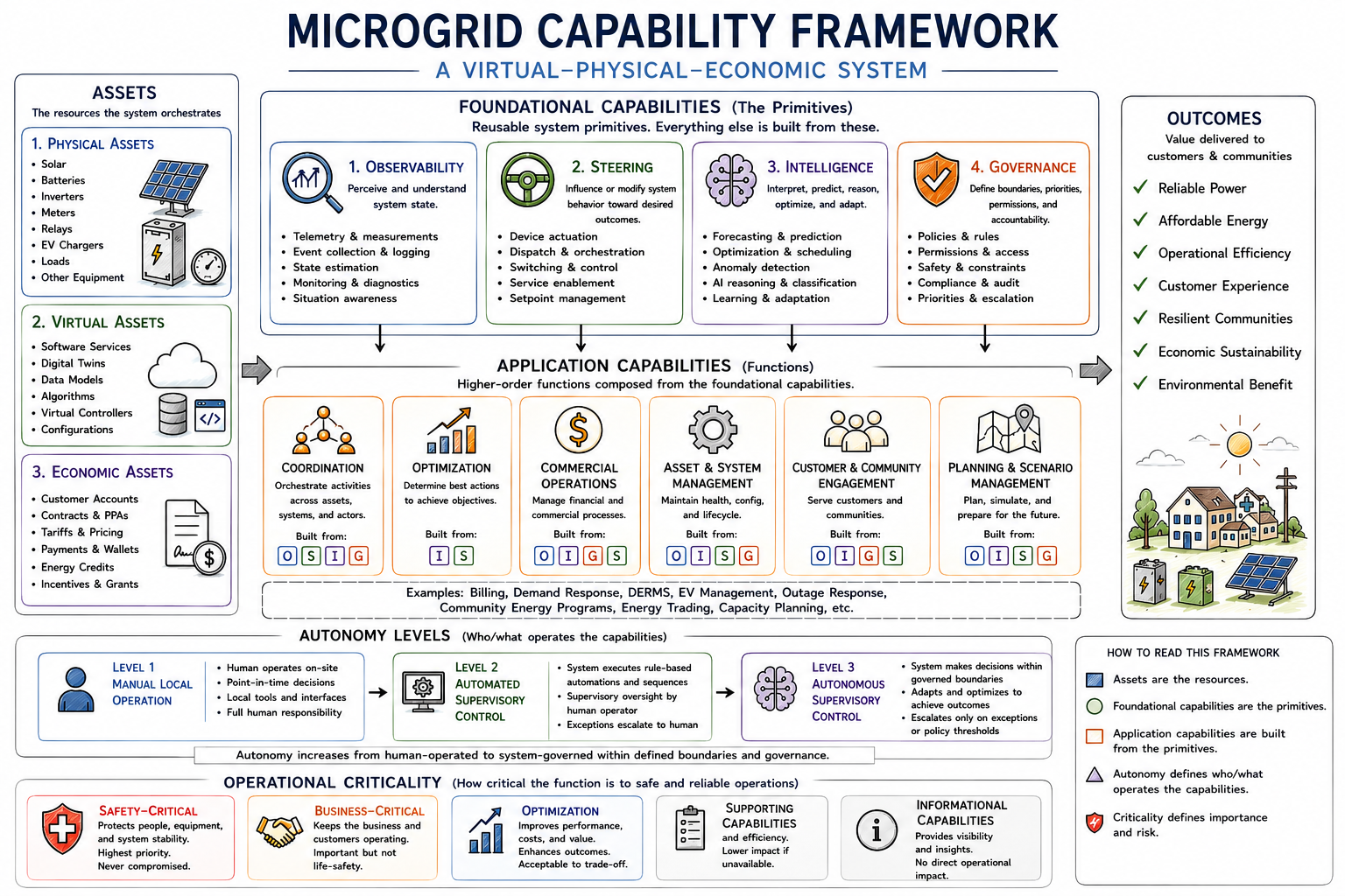
Introduction
As distributed energy resources become increasingly software-defined, microgrids are evolving from manually operated electrical systems into digitally coordinated energy platforms. This evolution creates a need for a clear framework describing the degree of operational autonomy assigned to different microgrid functions.
This document proposes a simple three-level autonomy model for microgrids inspired by concepts from industrial automation, supervisory control systems, and autonomous systems engineering.
Unlike autonomous vehicle frameworks that classify an entire vehicle into a single automation level, this framework applies autonomy levels to specific operational capabilities operating on specific assets.
For example:
-
Observing smart meter consumption
-
Steering battery dispatch
-
Observing EV charger utilization
-
Steering flexible loads
-
Forecasting solar production
Each capability may operate at a different level of autonomy.
A microgrid could therefore simultaneously contain:
-
Level 3 autonomous battery steering
-
Level 2 remote EV charger steering
-
Level 1 manual generator operation
This capability-oriented approach allows microgrids to evolve incrementally toward higher levels of operational autonomy.
Core Concepts
Assets
Assets are physical, digital, or economic components participating in the operation of the microgrid.
This framework groups assets into three primary categories.
1. Physical Assets
Physical assets are hardware systems that generate, store, distribute, consume, or protect electrical energy.
Examples include:
-
Smart meters
-
Battery energy storage systems (BESS)
-
Solar PV inverters
-
EV chargers
-
Diesel generators
-
Protection relays
-
Flexible loads
-
Distribution transformers
-
Remote disconnect relays
2. Digital Assets
Digital assets are software systems, communications systems, and computational services used to monitor, coordinate, optimize, and operate the microgrid.
Examples include:
-
Billing systems
-
Tariff engines
-
Payment systems
-
Forecasting systems
-
Customer identity systems
-
AI orchestration systems
-
SCADA platforms
-
DERMS platforms
-
Telemetry databases
-
Mobile applications
-
Notification systems
3. Economic and Contractual Assets
Economic and contractual assets represent the financial, commercial, and policy relationships governing the microgrid.
Examples include:
-
Customer accounts
-
Energy credits
-
Tariff structures
-
Power purchase agreements (PPAs)
-
Service tiers
-
Demand response agreements
-
Payment obligations
-
Credit limits
-
Utility interconnection agreements
These asset categories recognize that modern microgrids are not purely electrical systems. They are virtual-physical-economic systems integrating energy infrastructure, software platforms, and operational business logic into a unified operational environment.
Foundational Capabilities
Foundational capability domains are the core operational primitives from which higher-order microgrid behaviors and applications are constructed.
Rather than treating every operational function as a separate foundational capability, this framework identifies a small set of core capabilities that can be composed together to create more advanced orchestration, optimization, commercial, and autonomous behaviors.
These foundational domains operate across physical, digital, and economic assets.
1. Observability
Observability capabilities measure, record, analyze, and communicate system state.
Observability forms the awareness layer of the microgrid.
Examples:
-
Reading smart meter consumption
-
Monitoring battery state of charge
-
Detecting inverter faults
-
Measuring feeder voltage and frequency
-
Monitoring EV charging sessions
-
Customer usage analytics
-
Payment status monitoring
-
Event logging and telemetry collection
2. Steering
Steering capabilities execute operational actions intended to guide system behavior toward desired operational outcomes.
Unlike traditional low-level control systems, steering emphasizes adaptive orchestration, policy-driven operation, and outcome-oriented system management across distributed assets.
Steering forms the action layer of the microgrid.
Examples:
-
Disconnecting a load
-
Dispatching battery storage
-
Curtailing solar generation
-
Starting a backup generator
-
Setting EV charging limits
-
Executing demand response actions
-
Remote relay switching
-
Service disconnection and reconnection
3. Intelligence
Intelligence capabilities generate predictions, recommendations, classifications, reasoning, and adaptive operational decisions.
Intelligence forms the reasoning layer of the microgrid.
Examples:
-
Solar production forecasting
-
Load forecasting
-
Predictive maintenance
-
Fault prediction
-
Fraud detection
-
Adaptive operational policy selection
-
AI-driven energy management
-
Anomaly detection
-
Optimization modeling
4. Governance
Governance capabilities define and enforce operational rules, permissions, priorities, compliance requirements, and safety boundaries.
Governance forms the constitutional layer of the microgrid.
Examples:
-
Access control
-
Human override policies
-
Safety constraints
-
Regulatory compliance
-
Escalation policies
-
Operational audit logging
-
Cybersecurity enforcement
-
Service disconnection policies
-
Critical load protections
Application Capabilities
Operational application domains are higher-order business and operational functions constructed from combinations of the foundational capabilities.
These applications are not themselves foundational primitives. Rather, they emerge from orchestrating observability, steering, intelligence, and governance capabilities together.
Coordination
Coordination capabilities orchestrate workflows across systems, users, assets, and operational processes.
Coordination typically combines:
-
Observability
-
Steering
-
Governance
Examples:
-
Human escalation workflows
-
Multi-device orchestration
-
Customer notification systems
-
Utility coordination
-
Maintenance scheduling
-
Service provisioning workflows
-
Incident response coordination
Optimization
Optimization capabilities improve operational efficiency, economics, reliability, or customer experience.
Optimization typically combines:
-
Intelligence
-
Steering
Examples:
-
Energy arbitrage optimization
-
EV charging optimization
-
Demand response coordination
-
Forecast-driven battery dispatch
-
Load balancing
-
Power quality optimization
-
Asset utilization optimization
Commercial Operations
Commercial operations capabilities manage the economic and business functions of the microgrid.
Commercial operations typically combine:
-
Observability
-
Steering
-
Intelligence
-
Governance
Examples:
-
Customer billing
-
Tariff management
-
Payment processing
-
Credit management
-
Revenue collection
-
Energy credit accounting
-
Invoice generation
-
Service eligibility evaluation
-
Automated service disconnection and reconnection
Automation vs Autonomy
The distinction between automation and autonomy is foundational to this framework.
Automation
Automation refers to systems that execute predefined instructions or workflows under human-defined logic.
Examples:
-
Fixed battery charging schedules
-
Rule-based generator startup
-
Threshold-based load shedding
-
Remote switching by operators
-
Scheduled EV charger limits
An automated system follows instructions.
Autonomy
Autonomy refers to systems capable of independently managing operational objectives under changing conditions while operating within defined technical, economic, and safety constraints.
Examples:
-
Optimizing battery dispatch based on tariffs, weather forecasts, and outage probability
-
Dynamically prioritizing critical loads during constrained operation
-
Coordinating EV charging across multiple users to minimize peak demand
-
Predictive fault response and recovery
-
Adaptive energy management based on real-time conditions
An autonomous system manages outcomes.
Levels of Operational Autonomy
This framework distinguishes between:
-
Manual local operation
-
Automated supervisory control
-
Autonomous supervisory control
Level 1 — Manual Local Operation
At Level 1, foundational capabilities are operated directly by humans physically present at the asset location.
The asset itself provides the operational interface.
Examples:
-
Reading values directly from a smart meter display
-
Manually operating breakers or disconnects
-
Physically starting a generator
-
Local inverter configuration
-
On-site battery inspection
Operational Characteristics
| Question | Answer |
|---|---|
| Who monitors the system? | Human operators on-site |
| Who makes decisions? | Human operators on-site |
| Who executes actions? | Human operators on-site |
| Who handles failures? | Human operators on-site |
Characteristics
-
No remote supervisory capability
-
Human-driven operational awareness
-
Minimal software orchestration
-
Typically isolated or standalone systems
Relevant Standards
Relevant standards may include:
-
IEEE 1547 for DER interconnection behavior
-
IEEE 2030.7 for microgrid controller functional specification
-
IEC 61850 for power system communication models
At Level 1, however, most operational authority remains local and manual.
Level 2 — Automated Supervisory Control
At Level 2, foundational capabilities are supervised remotely through software platforms and communications networks.
Humans remain responsible for operational decisions, while software automates telemetry collection, visualization, alarms, workflows, and execution of predefined control logic.
Examples:
-
Remote smart meter monitoring
-
SCADA-based microgrid supervision
-
Rule-based battery dispatch
-
Remote EV charger management
-
Automated threshold alarms
-
Scheduled load control
Operational Characteristics
| Question | Answer |
|---|---|
| Who monitors the system? | Human operators remotely |
| Who makes decisions? | Human operators remotely |
| Who executes actions? | Automated systems under human-defined logic |
| Who handles failures? | Human operators with software assistance |
Characteristics
-
Remote visibility and control
-
Centralized supervisory software
-
Deterministic rule-based workflows
-
Human approval remains central
-
Software improves operational efficiency but does not independently manage system objectives
Relevant Standards
This level aligns closely with existing industrial automation and microgrid supervisory standards including:
-
IEEE 2030.7 — Specification of Microgrid Controllers
-
IEEE 2030.8 — Testing of Microgrid Controllers
-
IEC 61850 — Power system communication models
-
DNP3 and Modbus — Telemetry and control protocols
-
OpenADR — Demand response coordination
Level 2 corresponds closely to modern SCADA and DERMS architectures.
Level 3 — Autonomous Supervisory Control
At Level 3, foundational capabilities are operated autonomously by software systems capable of independently managing operational objectives within defined technical, economic, and safety constraints.
Humans define policies, operating boundaries, escalation procedures, and override authority, but the system continuously makes operational decisions without requiring constant human supervision.
Examples:
-
AI-driven battery optimization
-
Autonomous load orchestration
-
Dynamic outage response
-
Self-optimizing EV charging coordination
-
Predictive maintenance actions
-
Autonomous islanding and reconnection
-
Adaptive tariff-aware energy management
Operational Characteristics
| Question | Answer |
|---|---|
| Who monitors the system? | Autonomous software systems with human oversight |
| Who makes decisions? | Autonomous systems operating within defined policies |
| Who executes actions? | Autonomous software systems |
| Who handles failures? | Autonomous systems first, humans upon escalation |
Characteristics
-
Goal-oriented operational behavior
-
Context-aware decision making
-
Forecast-driven optimization
-
Dynamic adaptation to changing conditions
-
Human escalation rather than continuous supervision
-
Continuous optimization across multiple objectives
Key Requirements
Level 3 systems should include:
-
Human override capability
-
Policy enforcement mechanisms
-
Audit logging
-
Cybersecurity protections
-
Fallback operational modes
-
Confidence scoring and escalation logic
-
Safety envelopes and operational constraints
Relevant Standards
Existing standards partially address autonomous operation today. Relevant references include:
-
IEEE 2030.7 and 2030.8
-
IEC 62351 — Power system cybersecurity
-
NIST Cybersecurity Framework
-
Emerging AI governance and operational safety standards
Further industry standardization may be required to fully define autonomous microgrid operation.
Operational Criticality
Not all microgrid capabilities carry the same operational importance or risk.
This framework distinguishes between different classes of operational criticality.
Safety-Critical Capabilities
Capabilities whose failure or misuse could threaten human safety, equipment safety, or grid stability.
Examples:
-
Protection relay operation
-
Islanding and reconnection
-
Overcurrent protection
-
Emergency load shedding
-
Battery thermal protection
-
Voltage and frequency stabilization
These capabilities typically require strict operational constraints, auditability, and human override mechanisms.
Business-Critical Capabilities
Capabilities necessary for the commercial and operational sustainability of the microgrid business.
Examples:
-
Customer billing
-
Payment processing
-
Remote service disconnection
-
Tariff enforcement
-
Revenue collection
-
Customer account management
These capabilities are operationally important but must remain subordinate to safety-critical protections.
Optimization Capabilities
Capabilities intended to improve efficiency, economics, customer experience, or asset utilization.
Examples:
-
Energy arbitrage optimization
-
EV charging optimization
-
Demand response coordination
-
Forecast-driven battery dispatch
-
Predictive maintenance
-
Customer energy recommendations
Optimization capabilities should degrade gracefully without compromising safety or core operations.
Supporting Capabilities
Capabilities that support operational continuity, efficiency, maintenance, coordination, or administrative workflows, but whose temporary failure does not immediately compromise safety or core service delivery.
Examples:
-
Maintenance scheduling
-
Reporting systems
-
Asset inventory management
-
Customer notifications
-
Workforce coordination
-
Historical analytics
-
Non-critical integrations
Supporting capabilities improve operational effectiveness and resilience but are generally lower priority during constrained or degraded operations.
Informational Capabilities
Capabilities whose primary purpose is visibility, insights, diagnostics, learning, or reporting without direct operational authority over the system.
Examples:
-
Dashboards
-
Historical reporting
-
Data visualization
-
Energy usage insights
-
Community analytics
-
Educational interfaces
-
Public transparency portals
Informational capabilities provide situational awareness and decision support but typically do not directly influence operational behavior.
Applying the Framework
The framework is intended to classify autonomy at the capability level rather than the whole microgrid level.
Example:
| Asset | Foundational Capability Domain | Operational Function | Autonomy Level |
|---|---|---|---|
| Smart Meter | Observability | Usage telemetry | Level 2 |
| Battery Storage | Steering | Battery dispatch | Level 3 |
| Diesel Generator | Steering | Generator operation | Level 1 |
| EV Chargers | Observability | Charger monitoring | Level 2 |
| EV Chargers | Steering | Charging orchestration | Level 3 |
| Billing System | Commercial Operations | Automated billing | Level 2 |
| Smart Relay | Steering | Service disconnection | Level 3 |
This allows gradual evolution toward autonomy without requiring the entire microgrid to transition simultaneously.
Implications for a Microgrid OS
A Microgrid OS designed around this framework should:
-
Treat foundational capabilities as modular services
-
Support mixed autonomy levels simultaneously
-
Allow policy-driven escalation to humans
-
Maintain secure telemetry and control channels
-
Provide auditability and operational transparency
-
Support standards-based interoperability
-
Maintain operational safety boundaries
-
Support both edge and cloud orchestration architectures
The Microgrid OS becomes the orchestration layer coordinating assets, capabilities, policies, and autonomy levels across the energy system.
Metering protocols: DLMS/COSEM, OBIS, Modbus, MQTT (and NFE CHINT register map)
Traceable explainer: how metering data actually moves, where DLMS/COSEM, OBIS, Modbus, MQTT and HTTP each sit, and how NFE's live CHINT registers map to the OBIS standard vocabulary. Compiled 2026-08-10. Companion to "NFE metering strategy + Glen Street-EMS".
The layer cake (mental model)
Networking is layers. Each solves one problem and talks only to the layer above and below.
| Layer | Job | Examples |
|---|---|---|
| Link | move bits over one physical medium | RS485, Ethernet, WiFi |
| Network (IP) | address and route between any machines | IP |
| Transport (TCP) | reliable, ordered byte-stream between two programs | TCP, UDP |
| Application | what the two programs actually say | HTTP, MQTT, Modbus, DLMS |
Key point: MQTT, HTTPS and DLMS/COSEM are all application-layer. MQTT and HTTPS run on top of TCP (transport) on top of IP (network). MQTT is NOT a transport or network protocol.
One clean way to hold it all: IP gets you to the right building. TCP is registered mail that guarantees the whole message. Modbus/DLMS is the local interview with one meter (DLMS adds a shared vocabulary and an ID badge). OBIS/COSEM/SunSpec is that shared vocabulary. MQTT is the courier network carrying notes across the village and orders back. HTTP is a different courier that only does "go fetch one thing and return".
- MQTT: application, over TCP, port 1883 (8883 with TLS)
- HTTPS: HTTP + TLS over TCP, port 443
- DLMS/COSEM: application; rides serial (HDLC) OR TCP/IP directly
- Modbus RTU (NFE's meter to Pi link): application, straight over RS485 serial, no IP at all (why it is the simplest thing on site)
Three separate jobs, often confused
- Vocabulary (what a value means): OBIS / COSEM for meters, SunSpec for inverters.
- Local interrogation (talk to one device): Modbus or DLMS.
- Messaging (move data between many nodes, up and down): MQTT or HTTP.
You put COSEM-modelled data inside an MQTT message. They are not competitors: MQTT is the envelope, COSEM is the language on the page.
MQTT vs HTTPS
- HTTPS is request/response, pull: client asks, server answers, one round trip. The server cannot easily push to a device.
- MQTT is publish/subscribe through a broker, push: a device holds one persistent TCP socket to a broker and publishes to a topic; subscribers get pushed the message instantly. Tiny 2-byte header, QoS levels, retained last value, last-will (detect a dead node), pushes both ways (telemetry up, commands down), survives flaky low-bandwidth links.
- The Street-EMS village dashboard uses MQTT: it pushes "TURN OFF SSR0" down to a specific cabinet on topic
openami/StreetPoleEMS_<id>/cmdwhile readings stream up.
MQTT over the internet? Yes, it is just TCP. Devices make an outbound connection to a broker, so no inbound port-forwarding through the site modem, ideal for field gear on cellular.
Why not DLMS/COSEM over HTTPS? It buys nothing: DLMS already has its own TCP transport and its own message-level crypto (AES-128-GCM). And DLMS is a point-to-point session with one meter, not a fan-in/out telemetry bus. So the natural split is DLMS or Modbus to talk to the meter locally, MQTT to move the results around.
DLMS/COSEM, unpacked
- COSEM (Companion Specification for Energy Metering) is the data model: every value is an object of an interface class (Register, Profile Generic for load profiles, Clock, Disconnect Control for the relay, etc.).
- OBIS (OBject Identification System) names each object with a six-group code A-B:C.D.E.F. Example:
1-0:1.8.0= total active energy imported (what you bill). - DLMS (Device Language Message Specification) is the protocol: GET an attribute, SET an attribute, ACTION a method, inside an authenticated, encrypted association.
- Standardised as IEC 62056. Certified by the DLMS User Association.
The distinction: Modbus register vs COSEM "register"
A meter does NOT contain Modbus registers and COSEM registers side by side. They are two alternative languages for the same physical measurements. A given meter speaks one (or, on high-end dual-interface meters, both via separate ports).
- Modbus register = a numbered 16-bit memory slot at an address (e.g.
0x2004). Dumb storage. It is meaningless without the vendor manual telling you "0x2004 is active power". The meaning lives in a PDF, not in the data. - COSEM Register (object) = a self-describing object that carries its own unit and scaler, addressed by a global OBIS code that means the same thing on every compliant meter. (COSEM has an interface class literally named "Register", class_id 3 - hence the word collision. It is an object, not a memory slot.)
NFE's CHINT DDSU666 / DTSU666 are Modbus-only meters: inside them there are only Modbus registers, no COSEM, no OBIS. The OBIS column below is a translation NFE applies in software (in the logger / EMS / OpenAMI layer); the meter itself never knows about OBIS. The value of doing it: the meaning stops living in the CHINT manual and becomes the industry-standard, self-describing vocabulary.
NFE CHINT register to OBIS map
Single-phase DDSU666 (tenant meters, one phase). Source: nfe-modbus-energy-logger/src/meter_reader.py and the OpenEMS Meter.Chint.DDSU666 driver.
| Quantity | Modbus register (float) | OBIS code | Meaning |
|---|---|---|---|
| Voltage | 0x2000 | 1-0:32.7.0 | Instantaneous voltage L1 |
| Current | 0x2002 | 1-0:31.7.0 | Instantaneous current L1 |
| Active power | 0x2004 | 1-0:1.7.0 | Instantaneous active power (import +) |
| Power factor | 0x200A | 1-0:13.7.0 | Power factor |
| Frequency | 0x200E | 1-0:14.7.0 | Frequency |
| Import energy | 0x4000 | 1-0:1.8.0 | Total active energy imported (billing) |
| Export energy (invert cfg) | 0x4000 | 1-0:2.8.0 | Total active energy exported |
Three-phase DTSU666 (aggregate meter_100):
| Quantity | Modbus register(s) (float) | OBIS code(s) | Meaning |
|---|---|---|---|
| Voltage L1/L2/L3 | 0x2006 (x3) | 32.7.0 / 52.7.0 / 72.7.0 | Instantaneous phase voltages |
| Current L1/L2/L3 | 0x200C (x3) | 31.7.0 / 51.7.0 / 71.7.0 | Instantaneous phase currents |
| Active power total + L1/L2/L3 | 0x2012 (x4) | 1.7.0 / 21.7.0 / 41.7.0 / 61.7.0 | Instantaneous active power |
| Power factor | 0x202A | 13.7.0 | Power factor total |
| Frequency | 0x2044 | 14.7.0 | Frequency |
| Import energy | 0x4000 | 1-0:1.8.0 | Total active energy imported |
Note: the DDSU666 driver reads active power as already scaled kW; the DTSU666 needs per-manual scaling (Table 11: V/10, I x0.001, P x0.0001, PF x0.001, F x0.01). Minor code note: the logger's DTSU REGISTERS dict lists PF at 0x2020 but read() polls 0x202A; 0x202A is the one in use.
Why two OpenEMS drivers (meter and inverter)
Two physical devices with different proprietary Modbus maps means two drivers:
- CHINT meter (
MeterChintDdsu666Impl) reads 0x2000+; implements theElectricityMeterNature. - SRNE inverter (
SrneEssImpl) reads a totally different map at 0x0100 (SoC), 0x0101 (voltage), 0x0102 (current); implements theSymmetricEss/HybridEssNatures.
OpenEMS "Natures" (ElectricityMeter, SymmetricEss) are abstract interfaces both drivers map into, so the rest of OpenEMS sees a uniform API regardless of vendor. That is the local equivalent of what OBIS/COSEM and SunSpec do industry-wide.
The real prize of the standards is not one driver for meter plus inverter. It is one driver per device TYPE that works across every compliant vendor: any DLMS meter uses the same meter driver, any SunSpec inverter the same inverter driver. That removes the per-vendor Modbus-map work NFE did for both the CHINT and the SRNE. OpenEMS Natures give that uniformity on the edge (after the driver); DLMS and SunSpec give it at the wire (removing the driver work).
OBIS vs profiles (IDIS / OpenAMI): naming is not interoperability
OBIS names things, it does not force a meter to implement or behave the same way. DLMS/COSEM is a large, flexible toolkit and leaves most choices to the manufacturer: which OBIS objects are actually present, which data types and scalers, which security suite, which communication profile, which optional events. So two meters can both be DLMS/COSEM compliant and both use OBIS and still not interoperate out of the box. Compliant is not the same as interoperable.
IDIS (Interoperable Device Interface Specifications) is an industry association profile that sits on top of DLMS/COSEM/OBIS and removes the optionality: it mandates exactly which OBIS objects must be present and how they behave, the data types, security and events, a fixed communication profile, and an interoperability certification (conformance plus multi-vendor testing). Packages by transport: Package 1 (basic, local/optical + core residential objects), Package 2 (power-line comms PRIME/G3 + data concentrators), Package 3 (cellular/IP). Any two IDIS-certified devices genuinely interchange.
Mental model: DLMS/COSEM is the grammar and a giant dictionary with optional dialects; OBIS gives every word one fixed meaning; IDIS is a mandated phrasebook plus accent everyone certifies to, so a whole conversation is portable, not just the words.
Why it matters here: even if two meters both spoke OBIS, if they exposed different object sets over different links you would still write per-vendor glue (the same thing that produced two OpenEMS drivers). A profile is what makes "buy any certified meter, one driver, plug and play" real. IDIS is the heavyweight, utility-grade version of exactly what OpenAMI aims to be for off-grid villages: a mandated, open, lightweight village-metering profile on top of the vocabulary. NFE does not need full IDIS, but it does need a profile, and that is OpenAMI's whole purpose.
How OpenAMI sits on top
OpenAMI (IEEE Smart Village) is the actionable, utility-facing telemetry layer above a village feeder. It does not reinvent meter semantics: it composes OBIS/DLMS/COSEM (meters), SunSpec (inverters/DER), MQTT (transport), IEEE 2030.5 and 1547 (DER control). Its value-add is two-way, village-edge, policy-driven control and a billing cache, run cloudlessly and cheaply.
Sources
Element room "Smart Village Energy Interest Group"; isv.wiki; nfe-modbus-energy-logger/src/meter_reader.py; OpenEMS drivers io.openems.edge.meter.chint.ddsu666 and io.openems.edge.ess.srne; IEC 62056 (DLMS/COSEM); DLMS User Association Blue Book (OBIS).
Inverter-monitor notifications: hardening + tuning (ADR-012)
How the NFE inverter-monitor decides what to alert on, and the 2026-08-10 hardening pass that killed the nightly "Battery low" noise and closed several alert-integrity gaps. Source of truth is the code + ADR-012 in nfe-modbus-energy-logger; this is the team-facing summary.
What triggered it
A "[NFE Nansana] Battery low - below 80 percent" email fired at 79% while the battery was doing normal peak-window arbitrage. 79% is not low; 80% was simply in the alert threshold set, which a normally-cycling battery crosses every evening. An end-to-end review found that plus several real gaps.
What changed (all live on the VM)
- Thresholds 80,50,30,20,10 -> 30,20,10. 80/50 crossed nightly on normal arbitrage. Alerts now fire only at genuinely-low SoC. Override per site with
MONITOR_SOC_THRESHOLDS. - Debounce is now actually wired. A repeat/oscillating low-SoC crossing is suppressed within a cooldown (
MONITOR_SOC_DEBOUNCE_SECONDS, default 6h). It existed and was tested but had never been connected. - Severity scales with the level. A 30% crossing is a WARNING (amber); at or under 10% it is CRITICAL (red). Not every low-SoC is the same red alarm anymore.
- Silent-outage closed. A dead inverter/link while the Pi stays up used to be invisible (the heartbeat kept firing). New
data_stale(critical) /data_restoredalerts cover it, after N failed reads (MONITOR_DATA_STALE_AFTER, default 3), debounced. The old "Inverter offline" is renamed "Monitor offline" - it only ever meant the Pi/host/network is down. - No more false outages from one bad frame. A grid/battery source change now needs N consecutive readings to confirm (
MONITOR_GRID_CONFIRM_CYCLES, default 2). A single corrupt Modbus frame can no longer email a false grid-lost/restored pair. - Boot-into-low-SoC now alerts (previously silent until it recovered and re-crossed). grid_restored shows the outage duration.
- Delivery is retried. A one-cycle notifier or SMTP blip no longer silently drops a grid_lost - both the POST and the SMTP send retry.
- Security. The notifier refuses to bind a non-loopback interface with an empty token, so the /alert endpoint (which emails the whole team) can never be exposed unauthenticated.
The alert ladder (unchanged rungs)
- CRITICAL (red): monitor offline, data stale, SoC at/under 10%, battery empty, fault.
- WARNING (amber): grid lost (on battery), SoC below a threshold above the floor, over-temp.
- RESOLVED (green): grid restored, back online, data restored.
- INFO (blue): daily energy/arbitrage summary. Charge/discharge start-stop do not email individually.
Deploy + rollback
Built from merged main and deployed to the NFE OpenEMS VM as nfe-monitor:local + nfe-notifier:local (local build; the GHCR pipeline path unlocks once the nfe-monitor package is public). Previous images tagged :prev for rollback (docker tag nfe-monitor:prev nfe-monitor:local && docker compose up -d). Verified live: both containers stable (0 restarts), notifier listening + auth enforced (bad token -> 401), monitor heart-beating.
Traceable in repo
ADR-012-notification-hardening, docs/inverter-monitor.dsl (C4 model), docs/notification-severity-standard.md, PR #69. 255 tests, 99% coverage.
SRNE TOU arbitrage: plan (#67)
The plan to turn on time-of-use battery arbitrage on the Sezibwa/Nansana SRNE inverter (logger issue #67): charge the battery from the grid off-peak, discharge it to the load at peak, using the SRNE charge/discharge SCHEDULE registers written through the guarded write path we proved with #53. Compiled 2026-08-11.
The gap (why we are leaving money on the table)
The inverter already CHARGES off-peak (charge window is set to 00:00-06:00) but it does NOT discharge at peak - the discharge time-windows are all 0 (off). Live-confirmed 2026-08-10: at peak the battery sat idle on grid at ~79% while ~1.3 kW of load was served straight from the grid. So we pay the peak grid rate for load we could have covered with cheap off-peak energy already sitting in the battery. Turning on the discharge window closes that.
The economics (Code 10.2, what NFE pays the utility)
| Period | Window | Rate (UGX/kWh) |
|---|---|---|
| Off-peak | 00:00-06:00 | 343.20 |
| Shoulder | 06:00-18:00 | 577.11 |
| Peak | 18:00-24:00 | 666.50 (Q3 2026) |
Arbitrage = buy at 343 off-peak, avoid ~666 at peak = ~320 UGX/kWh gross, minus battery wear. Usable battery ~10.49 kWh; discharging ~5-7 kWh at peak while holding a reserve gives a gross saving in the low thousands of UGX per day. The daily energy/cash summary (#26, already live) already computes charged kWh + buy cost, discharged kWh + value, wear, and net margin - so once this is on we MEASURE the real number, not guess.
The levers (SRNE registers, decoded firmware v925, RW)
Written through the same guarded path as #53 (SafeWriteHandler: default-off, verified-machine-state gate, one-shot FC16, readback-verified). Time encoding = hour*256 + minute (e.g. 18:00 = 4608, 06:00 = 1536).
| Function | Register(s) | Live (2026-08-09) | Target |
|---|---|---|---|
| Charge window 1 | 0xE026 / 0xE027 | 00:00-06:00 | keep (off-peak) |
| Charge windows 2/3 | 0xE028/E029, 0xE02A/E02B | unset | optional |
| Discharge windows 1/2/3 | 0xE02D-0xE032 | ALL 0 (off) | window 1 = 18:00-24:00 (peak) |
| Output priority | 0xE204 | 3 | confirm = battery-first in-window |
| Charge priority | 0xE20F | tbd | grid, off-peak |
| Switch-to-line SoC (reserve floor) | 0xE01F | 10 | raise to protect reserve |
| Switch-to-battery SoC | 0xE020 | 90 | tune |
| Discharge cutoff SoC | 0xE00F | 5 | hard floor |
| Inverter RTC | set 0xE034-0xE036 / read 0x020C-0x020E | must be correct | verify, set if drifted |
NOT available on this firmware (confirmed Illegal-data-address): real-time active-power dispatch (0xE047-0xE04D, 0xE400-0xE402). We do NOT need it - scheduling covers TOU arbitrage.
Safety framing: reserve vs savings (the core tension)
The site's PRIMARY mission is backup during grid outages. Discharging at peak spends reserve exactly in the evening window when outages are most likely. So arbitrage must never drain below a backup reserve. Policy: hold >= 50% reserve until 30 days of outage data are collected (per CUSTOM_CODE/CLAUDE.md), then revisit. The discharge must STOP at the reserve floor, not run down to the discharge-cutoff. Phase 1 confirms exactly which register enforces that floor on this firmware (the switch-to-line SoC band vs a per-window reserve). RTC accuracy is critical - a wrong clock means the windows fire at the wrong time.
The build (mirrors #53, which is proven)
Phase 1 - Prove the schedule-write path (DAYTIME, no customer disruption):
- Fresh bus-quiet mbpoll read of every schedule/RTC/reserve register above = current ground truth (stop edge + mbpoll, 5s settle, read, restart - the method from #53).
- Extend the SRNE OpenEMS component to expose the schedule + RTC + reserve registers as guarded-writable settings, reusing the SafeWriteHandler infra from #53.
- Safe live test: write an UNUSED, far-from-now discharge window (e.g. a mid-morning slot), verify the readback, restore it to 0. Verify RTC reads wall-clock; set if off. This proves writes land and read back without ever activating a real discharge in front of customers.
- Tests to the 90% coverage gate; ADR; PR; git -> deploy.
Phase 2 - Program the arbitrage schedule (DAYTIME, supervised):
- Through the guarded write config (gateway config -> deploy, no box edits): set discharge window 1 = 18:00-24:00, confirm charge window 1 = 00:00-06:00, set the reserve floor to protect 50%, confirm output/charge priority.
- Watch one full cycle live: does it discharge at peak (battery carries the load, grid draw drops)? does it stop at the reserve floor? does it recharge off-peak overnight?
Phase 3 - Measure + tune:
- The daily #26 summary reports the actual arbitrage margin each morning. Tune the window edges and reserve against real margin + the outage log (the 30-day rule before dropping reserve below 50%).
Guardrails (all carried from tonight's #53 discipline)
Live-test before commission. Daytime writes only. Guarded write path (default-off, verified-state gate, one-shot, readback-verified). git -> deploy, never hand-edit the box. Bus-quiet reads (stop edge + mbpoll + 5s). Reserve-first: backup mission beats savings.
Open questions Phase 1 must answer
- Which register actually enforces the reserve floor on v925 (switch-to-line SoC vs a per-window reserve field)?
- Is the inverter RTC accurate right now? (windows fail silently if not)
- Output-priority (0xE204=3) semantics on this firmware - does it put battery first inside a discharge window while grid is present?